Hello,
In this project I am making a lamp with multiple colors using RGB leds. My idea is to try to let the lamp change color if it detects a sound in the area. If you get annoyed from the changing colors every time you make a sound, you can always put the lamp on a mode where you can change the colors manual. Also the lamp will go off when you come too close to it.
The casing of the lamp is designed using Adobe illustrator and next cut out by a laser cutter.
This project will be explained to you in a few steps where I try to explain how you can build this lamp.
Here is a list of components you will need to create this lamp:
– 69 x RGB led
– 2 x Resistor 470 ohm
– 2 x Resistor 330 ohm
– 5 x Resistor 220 ohm
– 1 x Ultrasonic distance sensor
– 1 x On/Off switch
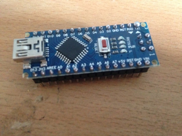
– 1 x Arduino Nano
– 3 x Small pushbutton
– 1 x Regular Led Red
– 2 x Experimental Plate copper
– 1 x Sound detection module
– Isolated wires
– Soldering wire
Step 1: The Casing
The lamp consists of multiple parts.
The first part is the casing. The casing will be build from wood. To make sure the casing’s dimensions are as precise as possible I’ll use a machine called a lasercutter. With this machine I can make the casing to a precision of a tenth of a millimeter. To work with the lasercutter I had to create my design in Adobe Illustrator (see the attached .ai files).
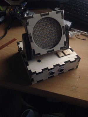
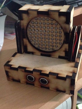
My design of the casing looks like a box. The idea to create the cut-outs is to make sure it will stay together when I am going to glue it. In the last picture above you can see how my final design will look like.
The little box consists of seven panels one square to contain the RGB leds, two squares for the back and the front and four rectangles for the sides. The one square is made of a 3mm thick wooden plate where all the holes for the RGB leds are cut into. The little holes are 5mm so the RGB leds will fit in nicely. The front, back and side panels are made from a 6 mm thick wooden plate. The front panel’s got a round shaped hole cut into it’s middle where you can see the RGB leds through. The two panels on the left and the right got a big and a little round shaped hole into it. The little hole is for pulling through the wires and the big hole is to ensure the lamp can rotate.
The big box consists of six panels shaped the same as the little bocx but bigger. The big box will be made to fit in the on/off switch, a power suplly, a distance sensor and the Arduino. The holes on the front of the box are made to fit in the two little ultrasonic speakers of the distance sensor.
In the .ai files you can see the dimension I’ve used to create this design.
Step 2: Soldering the RGB Leds
The next part of making the lamp is to solder the RGB leds.
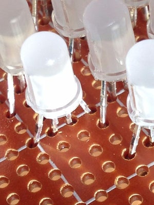
To make sure the RGB leds will stay on their place, I’ve used a experimental plate to solder the RGB leds. A RGB led has three legs beneath it’s head. The RGB leds I’ve used are Common Anode which mean they have the same Vcc and all the other legs have to be grounded differently. The longest leg is the Vcc. The one leg next to it is the red led, the leg next to it in the middle is the green led and the last leg is the blue led.
As you can see in the third picture above I’ve crossed some legs with eachother. This is to make sure the RGB leds will fit into the holes of the panel within the little box.
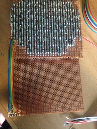
The RGB leds have to be soldered in rows. The rows comprise rows of five, seven and nine leds. If you did solder a led onto the plate you have to remove the remaining part of the leg with for example nippers. Once you finished soldering all the RGB legs onto the plate you can connect all the legs with the same function with eachother. Make sure you connect all the red legs with the red legs, the green legs with the green legs, the blue legs with the blue legs and the vcc legs with the vcc legs. Otherwise you wil get rows with different colors.
The next step is
Step 3: Soldering the Same Colors With One Another
The next step is to solder all the separated row of the same color or function together.
To do this you have to create a new experimental plate with the same size as the one you’ve used to solder the leds onto. Once you’re done doing that you can make four rows to connect the different colors to. Make sure you have got a wire sticking out from the rows that are long enough to reach trought the holes into the big box.
The first thing you have to do next is to solder a resistor from the Vcc rows to one of the rows you’ve created. Each Vcc row demands another current value so each row needs another resistor value. The rows with five leds requires 470 ohm resistors, the rows with seven leds requires 330 ohm resistors and the rows with nine leds requires 220 ohm resistors. Try to get solder the resistors first onto the plate to make sure you’ve got enough space left to solder the other rows.
When you’ve soldered all the legs with the same color or function to the four rows you’ve created at first you can start testing if your creation will work by giving a tension of 5 volts to the Vcc row. Then you have to ground each row separatly to test if your RGB leds will work with all the colors.
Without a Arduino you can’t get more than three colors right now!
Step 4: Putting the Case Together

If you’re done soldering and testing all of your RGB leds it’s time to put the case of the little box together.
Try to fit the RGB plate over your leds and glue it onto the front panel. Make sure you pulled the wires through the side panel’s holes and glue the together with the othe side panels and the back panel together.
Once the glue is dry and the box is stuck try to fit the two experimental plates into the created box. It will maybe be a little hard to fit everything in. Now glue the front panel onto the rest and let the glue take the time to dry. Once it is stuck you can let go of the front panel and your box will be ready.
To test all the different colors you’ve got to use the Arduino. In the attached file (Colortest.ino) you will find a test code for using the different colors.
Step 5: Building the Hardware and Casing of the Lower Box
This is the last step of building the lamp.
The lower box is the part of the lamp which controls the entire product. The lamp is controlled by a Arduino Nano microcontroller. All the excesive hardware is also programmed on this microcontroller.
The first thing you need to do in building the lower case is to create a sort of shield, to compare with a holder, for your Arduino where you can connect all your wires and other components on to. In the second picture you can see the shield I’ve created. Ive used female headers to put the Arduino in place. I also make use of terminal blocks(the blue blocks with an screw inside) to connect the wires easier. This is also an usefull way to connect and deconnect the wires without soldering it on and off again.
The second part is to solder two pushbuttons on a experimental plate which will be used for your status/modus and color select. Make sure the button has a pulldown resistor of 10K ohm on the output to make sure the button will not float. If the button floats your microcontroller will get very much inputs and because of that continue to change colors in a very fast frequency.
The third part is the distance and sound detection. The distance detection will be realised by a distance sensor called the HC-SR04. This sensor uses ultrasonic sound waves to determine the distance of the next object in it’s way. In my design I only use the distance sensor in the led fade state. This is because it freezes when it is in an other state. I still have to fix that :). In the file below you can find the function with the code that I used to determine the distance and to let the leds go off, and on again when you’re out of range.
The sound detection part uses a sound detection module. It doesn’t matter which sensor module you take because they all work very well. In my lamp I’ve programmed the sensor to be as sensitive as possible. The sensor reacted when I dropped a screwdriver on my desk so it is very sensitive. In the file below you can find the function soundDetect which contains my code how to use the sound module.
The last thing you need to do is to superglue all the walls of the box together and fit all the hardware components into it.
I hope you liked my project and be free to leave a comment 😉
Source: Sound Detection RGB Lamp Using Arduino