Overview:
The solar tracking device is designed to ensure that a flat panel with a solar cell is constantly aligned with the movement of the sun across the sky. It utilizes two light dependent resistors (LDRs) positioned on opposite sides of a fin to measure the light levels. By comparing the readings from the LDRs, the Arduino can determine the side that receives more illumination and adjust the position of the servo connected to the panel accordingly. The servo will rotate the panel until the two detectors have equal light levels. This Arduino project is an excellent combination of sensors and servos, incorporating logic that can be fine-tuned, and it serves a practical purpose in the field of clean energy.
![]()
Background:
Solar panels are most effective at generating electricity when they receive direct sunlight perpendicular to their surface. A solar tracker is a device that adjusts the position of the panel to continuously face the sun, maximizing energy production. By rotating the panel along one or two axes (altitude and azimuth), the tracker ensures that the panel is always aligned with the sun’s position in the sky. This is particularly important for concentrating or focusing collectors that require precise alignment with the sun to function optimally.
The solar tracker described here is a single-axis mount designed to track the sun’s movement from east to west. It features a rotating axis directed towards the North Star, known as an equatorial mount. This configuration allows the tracker to follow the sun’s path with a single rotation.
In the field of Earth science, it is observed that the sun moves across the sky at a rate of 15 degrees per hour due to the Earth’s rotation. During winter, the days are shorter, and the sun rises south of east, sets south of west, and has a low noon angle. In contrast, summer days are longer, and the sun rises north of east, sets north of west, and has a higher noon angle. The peak noon angle for the sun on the equinox is 90 degrees minus the latitude. At the summer solstice, it is 23.38 degrees higher than the equinox angle, and at the winter solstice, it is 23.38 degrees lower.
Research Connection:
Scientists and engineers are trying to increase the efficiency of solar cells and decrease the expense. Trackers were considered practical when solar cells were very expensive. Now prices have come down so much that the emphasis is on large areas of fixed panels and on covering all available building surfaces with panels. Concentrating solar thermal collectors use hundreds of mirrors which rotate to reflect light to central power tower. Solar thermal trackers are still relevant because they have the potential to store energy with molten salts for several hours after sun down. This helps deliver solar generated power in the evening when demand peaks.
NGSS Standards:
| MS-PS3-3 | Apply scientific principles to design, construct, and test a device that either minimizes or maximizes thermal energy transfer.* |
| MS-ESS1-1 | Develop and use a model of the Earth-sun-moon system to describe the cyclic patterns of lunar phases, eclipses of the sun and moon, and seasons. |
| 4-PS3-4 | Apply scientific ideas to design, test, and refine a device that converts energy from one form to another.* |
| HS-PS3-3. | Design, build, and refine a device that works within given constraints to convert one form of energy into another form of energy.* |
Materials:
- Arduino board, power supply, USB cable,
- 2 light dependent resistors (LDR) with the same resistance range
- Two 10K resistors
- Servo
- Cardboard, balsa, straight pins, wires, mounting screws
Introduction
To familiarize the students with the movement of the sun across the sky and its seasonal variations, review the concept of the sun’s apparent motion throughout the day and throughout the year. Help them understand that since the Earth completes a full rotation of 360 degrees in 24 hours, the sun appears to move across the sky at a rate of 15 degrees per hour. Engage the students in a mathematical exercise to demonstrate this relationship.
Next, encourage the students to develop design requirements for their solar tracking device. This may involve specifications such as the device rotating 15 degrees per hour to keep the solar panel aligned, adjusting both the altitude and azimuth angles, and resetting its position from the previous night in preparation for the next morning. By establishing these design requirements, the students can lay the foundation for creating their own functional solar tracking devices.
Assembly
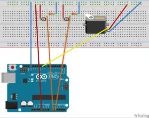
Connect each light dependent resistor (LDR) to a power supply of 3 or 5 Volts and to Pin A0 for one LDR, and connect it to a 10K resistor that is connected to ground. Connect the other LDR to Pin A1 and also to a 10K resistor connected to ground. This setup forms a voltage splitter, which provides variable voltages to the analog inputs based on the amount of light detected by each sensor.
To connect the servo, attach the brown wire to ground, the red wire to 5V, and the orange wire to digital pin 9.
If you are doing this as a class activity, it’s a good time to brainstorm a pseudo-code description of the program’s functionality. The basic logic would involve checking if the value from the left LDR is greater than the value from the right LDR, in which case the servo should turn one way, and if it’s the opposite, the servo should rotate the other way. It’s important to introduce a tolerance factor to account for small differences and prevent jittering due to fluctuating sensor measurements.
Convert the pseudo-code into actual code, starting with an example from the Arduino IDE library such as “Servo”. Load the program onto the Arduino board and test it to ensure that the servo responds correctly to light variations detected by the LDRs. If troubleshooting is needed, you can use the “digital write” function to check sensor values and the if-then statement.
Once you have confirmed the functionality on the breadboard, you can proceed to build the complete apparatus. Attach a piece of balsa to the servo mount arm using pins inserted through a hole into the end grain of the board. Mount the two LDRs on either side of the shading fin, which can be made from cardboard or balsa. Pass the leads of the LDRs through the appropriate holes for accessibility from the back.
Connect thin, flexible wires to the LDRs to minimize resistance during rotation. Cut a box diagonally and mount the top part by pressing a pin into a balsa strut at the top, and secure the servo using a pin and struts at the bottom. Set the axis angle to match your latitude.
To mount the Arduino, use small bolts to attach it to the side of the box, allowing for easy removal without causing damage. It is possible to wire this design using only the Arduino inputs without the need for a breadboard (insert the resistors into the A0 and A1 holes along with the LDR leads, and connect the resistors to ground).
Finally, test your finished apparatus. Adjust the delay in the code to make the response faster, and modify the tolerance value to enhance stability when the optimal position is reached.
Code Example
//Single axis solar tracker program
#include <Servo.h> // loads the servo library
Servo myservo; // create servo object to control a servo
int pos = 90; // variable to store the servo position 0-180
int sensorPin = A0; // select the input pin for the potentiometer
int sensorPin2 = A1;
int sensorValue = 0; // variable to store the value coming from the sensor
int sensorValue2 = 0;
int diffval = 0;
int errorval = 15;
void setup()
{
myservo.attach(9); // attaches the servo on pin 9 to the servo object
//Serial.begin(9600); // uncomment if you need to measure outputs with the serial monitor.
}
void loop() {
sensorValue = analogRead(sensorPin);
sensorValue2 = analogRead(sensorPin2);
diffval = sensorValue – sensorValue2;
if (abs(diffval) > errorval) {
if (diffval > 0) {
pos = pos + 5;
}
else {
pos = pos – 5;
}
myservo.write(pos);
delay(100);
}