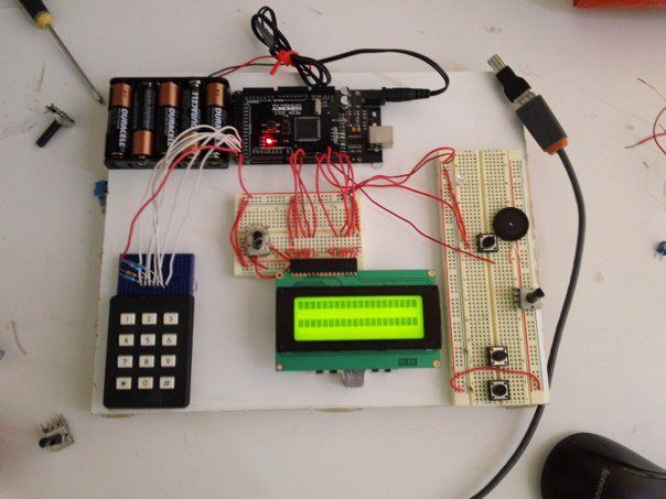
Summary of Password access with arduino
This tutorial explains building an Arduino Mega pass-code lock: an LCD displays status, a keypad inputs the code, and a servo plus LED actuate when the correct code is entered. It covers wiring the 16-pin LCD (including a contrast potentiometer), wiring a 3x4 keypad with pull-down/pull-up resistors, connecting a servo, and installing the Keypad and Password libraries before uploading the sketch.
Parts used in the Pass-code lock system:
- Arduino Mega
- LCD module (16-pin)
- Keypad (3x4)
- Battery pack or USB cable for power
- 10K Ohm potentiometer
- Four 10K Ohm resistors
- Breadboard
- Hookup wire
- Servo
This instructable will show you how to make a pass-code lock system using the Arduino Mega board.
Whenyou type the right code, an LED lights up an the servo moves to open a lock.
What you will need:
—>one Arduino Mega (the arduino uno or duemilianove does not have enough digital pins for this project)
—>one LCD module
—>one Keypad
—>one Battery pack (or you can use the USB cable and PC power)
—>one 10K Ohm potentiometer
—>four 10K Ohm resistors
—> Breadboard
—> hookup wire
—>one servo
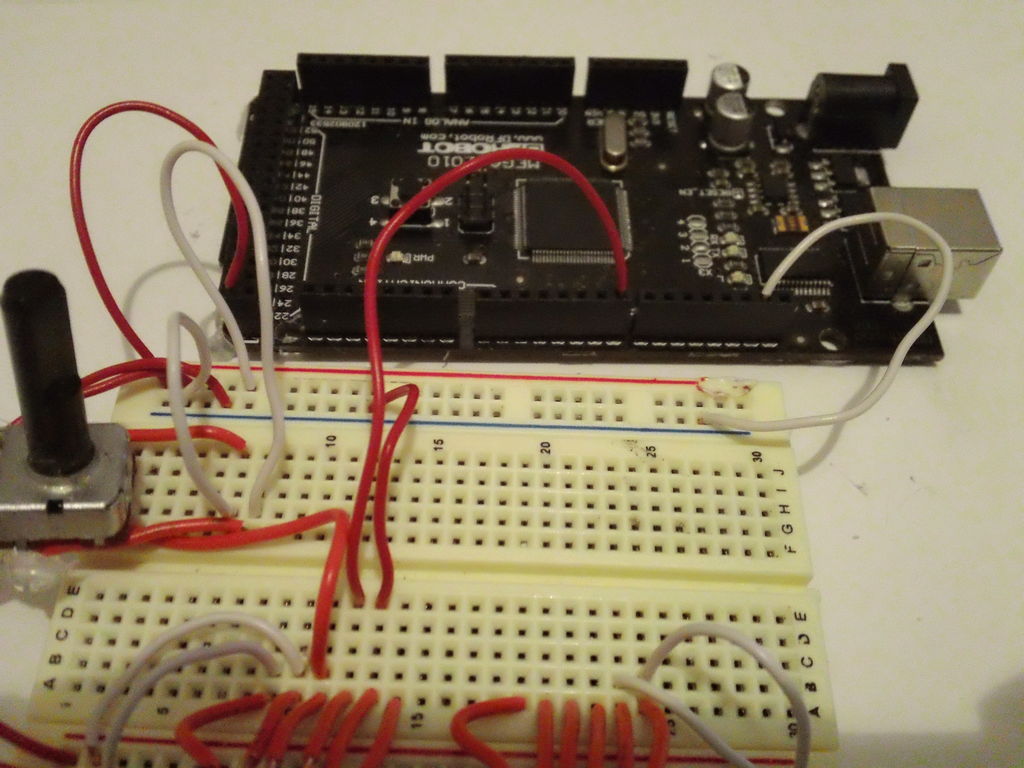
Step 1: Wire the LCD to the Arduino
First of all, connect pins 1 and 16 of the LCD to the ground rail on the Breadboard
Then connect pins 2 and 15 of the LCD to the +5v rail on the breadboard
Now connect the ground rail(should be blue) of the breadboard to a ground pin on the Arduino;
Connect the +5v rail of the breadboard(this one is red) to one of the +5v pins on the Arduino board.
Now comes the contrast potentiometer which has to be connected to pin 3 of the LCD.
The potentiometer will have 3 pins. Take the middle pin and connect it to pin 3 of the arduino with hookup wire. Connect the othere two pins one to +5v and the other to GND(ground). The order does not matter.
Now let’s do a test: power up the arduino. The LCD should light up. If it does then Great! If the LCD does not light up then turn off the power and check the wires.
Never change, move, or take out wires from the circuit board when the Arduino is powered up. You may permanently damage the Arduino.
If the light works rotate the potentiometer all the way to the right and all the way to the left until you see 2 rows of black squares. That’s the contrast.
Now take out the power and let’s hook up the LCD to the Arduino with the signal wires so we can display something on it.
Ready? Let’s go!
Connect the pins as follows:
LCD Pin 4 –> Arduino Pin 2
LCD Pin 5 –> Arduino Pin 3
LCD Pin 6 –> Arduino Pin 4
LCD Pin 11 –> Arduino Pin 9
LCD Pin 12 –> Arduino Pin 10
LCD Pin 13 –> Arduino Pin 11
LCD Pin 14 –> Arduino Pin 12
And that should do it for the LCD circuit.
A test code for the the LCD: temporary.
#include <LiquidCrystal.h>
// initialize the library with the numbers of the interface pins
LiquidCrystal lcd(2,3,4,9,10,11,12);
void setup() {
// set up the LCD’s number of columns and rows:
lcd.begin(16, 2);
// Print a message to the LCD.
lcd.print(“hello, world!”);
}
void loop() {
// set the cursor to column 0, line 1
// (note: line 1 is the second row, since counting begins with 0):
lcd.setCursor(0, 1);
// print the number of seconds since reset:
lcd.print(millis()/1000);
}
Copy and paste it in an arduino environment window, make sure you have the board and serial port set correct and click UPLOAD after you plug in the usb with the arduino.
You will see the TX and RX led’s blinking, that means the code is going to the arduino.
push the reset botton once on the arduino, tune the contrast, and you should see Hello World displayed.
Congratulations! You’ve got the LCD working! 🙂
Step 2: Wire the Keypad to the Arduino
If you have a keyboard that is made especially for connecting to an arduino, then it’s easy. You just look at the datasheet for it and it tells you exactly how to hook it up.
If you have a keypad and you have no datasheet for it then hang on cause I was in the same situation.
Mine had on the back a diagram that shows you which pins are connected together when you press a certain key.
If you don’t have that, you will have to use a multimeter and figure out which pins are connected together when you press each key.
To do that, take your multimeter and set it on continuity(the diode symbol).
Then put the test leads on pins 1 and 2 of the keypad. Now press every key until you get continuity.
Take paper and a pen and write down the key(ex:1, 2, #) and the two pins(ex: 6[1;2]).
Do so for every key until you get all of them figured out.
Make a table:
1=1+5
2=1+6
3=1+7
4=2+5
5=2+6
6=2+7
7=3+5
8=3+6
9=3+7
*=4+5
0=4+6
#=4+7
That is what I got.
Whatever you get, if you write down the keys in that order you will see the logic in it.
From my table I can see that the row pins are 1,2,3,4; and the column pins are 5,6,7.
Now plug the pins of the keypad in a breadboard and let’s start connecting it.
Connect the pins for rows 2 and 3( in my case pins 2 and 3) to +5v through 10K Ohm resistors. Do the same with the pins for column 1 and 3 pins( in my case pins 5 and 7).
If you have an arduino mega, connect the keypad as follows:
Keypad pin row1–> arduino pin 25
Keypad pin row2–> arduino pin 24
Keypad pin row3–> arduino pin 23
Keypad pin row4–> arduino pin 22
Keypad pin column1 –> arduino pin 28
Keypad pin column2 –> arduino pin 27
Keypad pin column3 –> arduino pin 26
(The arduino uno does not have enough digital pins so it does not fit this project.)
That should do it for the keypad. 🙂 we’re one step closer to finish. Hang in there. 🙂 Almost done.
Step 3: Connecting the servo
It has 3 wires: Red, Yellow(or white or orange), and black.
Connect the red wire to +5v, the black wire to GND, and the middle wire to digital pin 8.
That’s it for the servo.
Step 4: Preparations for coding
Before we put in the final code we have to make some modifications.
https://docs.google.com/leaf?id=0B8GceIlOmvRoNWZmNWExYTMtYjVmNS00MzE5LWFlMWQtNDM3MTY1MTcyZTUx&hl=en_US
G o to the link above and download the libraries: keypad and password.
They are two files. take the files and put them in /Arduino/Libraries.
if the download does not work for bizarre reasons, go to:
http://arduino.cc/playground/uploads/Code/Keypad.zip
http://arduino.cc/playground/uploads/Code/Password.zip
Read more: Password access with arduino
- Can I use an Arduino Uno for this project?
No, the Arduino Uno or Duemilanove does not have enough digital pins for this project; use an Arduino Mega. - What pins connect the LCD to the Arduino Mega?
Connect LCD pins 4,5,6,11,12,13,14 to Arduino pins 2,3,4,9,10,11,12 respectively. - How do I wire the LCD power and contrast?
Connect LCD pins 1 and 16 to GND, pins 2 and 15 to +5V, and the potentiometer middle pin to LCD pin 3 with its other pins to +5V and GND. - How do I determine keypad pin mapping if no datasheet?
Use a multimeter on continuity while pressing keys to record which keypad pins connect for each key, then infer rows and columns. - Which Arduino pins are used for the keypad on the Mega?
Connect keypad rows to Arduino pins 25, 24, 23, 22 and columns to pins 28, 27, 26 as described. - How should I wire the servo?
Connect servo red to +5V, black to GND, and signal (middle) wire to digital pin 8. - What libraries are required before coding?
Install the Keypad and Password libraries into the Arduino/Libraries folder as instructed. - How can I test the LCD after wiring?
Upload the provided LiquidCrystal test sketch, reset the board, adjust contrast, and verify Hello World displays and millis updates.