Summary of Solar Power Data Logger
This article details building a solar power data logger using an Arduino Uno and a PV cell to record voltage, time, and date on an SD card. The project involves constructing a custom aluminium stand for the panel and housing the electronics in an enclosure with a voltage divider circuit to monitor power yield under varying light conditions.
Parts used in the Solar Power Data Logger:
- Offgridtec 12V/5W Poly Solarpanel
- Diamond plate aluminium sheet 200x600x1,5mm
- Aluminium sheet 26x15x1,5mm
- Bolts M8x20mm
- Nuts M8
- Wingnuts M8
- Enclosure 115x90x55mm
- Mini Breadboard
- Resistor 18 Ohm / 2W
- Resistor 47 Ohm / 5W
- Feeder clip
- Arduino or Genuino Uno R3
- Adafruit data-logger-shield for Arduino
- USB Cable
- USB Battery Pack 5V/1A
- Piece of Plywood
- Cable 2x0,75mm2
- Wire end sleeves 0,75mm2
- Stacking headers for Arduino
- Screws and bushings
Ever wanted to know how much solar power you could yield by putting PV cells in a specific place on or around your house?
This Instructable shows you how to build a data logger based on an Arduino (or Genuino) Uno with data-logger-shield and a PV cell recording the electric power yielded during a sunny day or even longer.
The data (date, time, voltage,…) are recorded on an SD-card and can be edited with a spreadsheet software like MS-Excel.
1. Materials
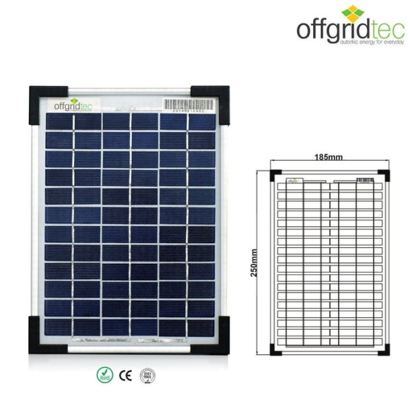
1.1 PV Cell
1 Offgridtec 12V/5W Poly Solarpanel
https://www.offgridtec.com/offgridtecr-5w-poly-sol…
1.2 Stand
1 Diamond plate aluminium sheet 200x600x1,5mm
2 Aluminium sheet 26x15x1,5mm (for screw lock)
2 Bolts M8x20mm
2 Nuts M8
2 Wingnuts M8
1.3 Data logger
1 Enclosure 115x90x55mm
1 Mini Breadboard
1 Resistor 18 Ohm / 2W
1 Resistor 47 Ohm / 5W
1 feeder clip
1 Arduino or Genuino Uno R3
1 Adafruit data-logger-shield for Arduino
https://learn.adafruit.com/adafruit-data-logger-sh…
1 USB Cable
1 USB Battery Pack 5V/1A (without smart charging technology)
1 Piece of Plywood
0,5m Cable 2×0,75mm2
4 wire end sleeves 0,75mm2
Stacking headers for Arduino, wires for breadboarding, screws, bushings
2. Tools
2.1 Stand and casing
vice
tape measure
tinsnips
hammer
electric drill and drillers 2mm, 3mm, 8,5mm and 12mm
file
wood saw
2.2 Data logger
soldering iron and solder
screwdrivers
pliers
cable stripper
computer with Arduino IDE
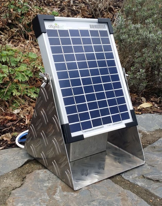
Step 1: Preparing the Stand and the Solar Panel
The stand is made out of an aluminium sheet of 1,5mm, bent in U-shape according to the size of the solar panel. The inclination of the panel can be adapted and locked with the two wing nuts and a screw locks inside the panel frame.
1. Draw the shape of the stand on the sheet.
2. Cut off the corners and bend it.
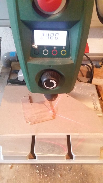
3. Drill the holes for the M8 bolts.
4. Prepare the screw locks.
5. Drill two holes of 8,5mm in the frame of the panel.
6. Assemble stand and solar panel.
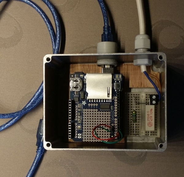
Step 2: Preparing the Voltage Divider and the Housing
The enclosure contains the electronic parts, Arduino Uno, data-logger-shield and the mini breadboard with the voltage divider.
The electronic parts are connected to the power supply of the Arduino, an USB battery pack and the solar panel.
1. Cut a piece of plywood according to the size of your casing. Make a cutoff for the mini breadboard.
2. Secure the Arduino on the plywood using three screws. (Mind to leave enough space for the SD card!).
3. Drill some aeration holes on both sides of the casing.
4. Drill two holes for the cables with diameter according to your bushes.
5. Put the resistors and the jumper wire on the mini breadboard.
The voltage divider (load) is calculated to provide 5V to the Arduino analog pin A0 when the solar panel reaches it´s maximum power point (MPP) under standard light intensity (0,28A and 17,6V under 1000W/m2). In practice, the 45 Ohm resistor has 47 Ohm and both resistors have tolerances (between 3 and 10%!). So, the operating point of the circuit does not meet exactly the MPP (see Voltage-current graph).
Anyway, the values of the resistors you want to use have to be checked in order to avoid voltages higher than 5V on the Arduino input.
Furthermore, modern PV modules work with so-called MPP-Trackers, inserted between solar panel and load, in order to ensure optimum operation under variable circumstances (temperature, light intensity). Our load stays constant which means that the amount of energy yielded with our data-logger will be slightly less compared to a complete PV module system.
Find more interesting information about the electrical characteristics of solar modules and MPP-trackers under
http://www.greenrhinoenergy.com/solar/technologies…
Step 3: Preparing the Data-logger-shield and Wiring
The Adafruit data-logger-shield lets you record data with date and time information. The data are stored on an SD card in a *.CSV-file, editable with a spreadsheet software. A backup battery keeps the clock working without external power supply.
Find a good documentation of the shield under
https://learn.adafruit.com/adafruit-data-logger-sh…
1. Solder the stacking headers on the shield.
2. Connect the two LEDs (solder pads “L1″L and “L2”) on the data-logger-shield to the digital pins 2 and 3 (L1 to pin 2 and L2 to pin 3).
3. Connect the 2×0,75mm2 cable to the panel and the voltage divider.
4. Assemble the Arduino board and the shield.
5. Connect the voltage divider to the Arduino board (GND [blue wire] and Analog Pin A0 [orange wire]).
Read more: Solar Power Data Logger
- What software is used to edit the recorded data?
The data stored on the SD-card can be edited with spreadsheet software like MS-Excel. - How is the inclination of the solar panel adjusted?
The inclination is adapted and locked using two wing nuts and a screw lock inside the panel frame. - Does the load stay constant during operation?
Yes, the load stays constant, which means the energy yielded will be slightly less compared to a system with an MPP-Tracker. - Why are resistor values checked before assembly?
Values must be checked to avoid voltages higher than 5V on the Arduino input due to resistor tolerances. - What format are the recorded files saved in?
The data are stored on an SD card in a *.CSV-file. - How does the backup battery function in the shield?
A backup battery keeps the clock working without external power supply. - Can this setup track maximum power point exactly?
No, because the load stays constant, the operating point does not meet exactly the Maximum Power Point (MPP). - Which pins connect the LEDs on the data-logger-shield?
L1 connects to digital pin 2 and L2 connects to digital pin 3.