Summary of Soft Squares – Chisel Away With Arduino in Unity
This student project creates a physical Arduino-powered chisel that interacts with a Unity game called "Soft Squares." Users sculpt a virtual 5x5x5 cube by physically swinging the device, which uses an accelerometer to detect motion. The controller features buttons and an optional joystick for camera movement and color selection, allowing players to paint and chip away digital blocks in real-time.
Parts used in the Soft Squares - Chisel:
- Arduino Uno Rev3
- USB 2.0 Cable Type A/B
- Joystick (optional)
- 4 or 5 2-pin Buttons
- 18 Male-Male Jumper Cables
- ADXL345 Accelerometer
- 2 Cable Lugs
- 3D Filament
- Solder
- Sanding Paper
For this project, I created an Arduino-powered chisel which can communicate with a game I made in Unity, Soft Squares.
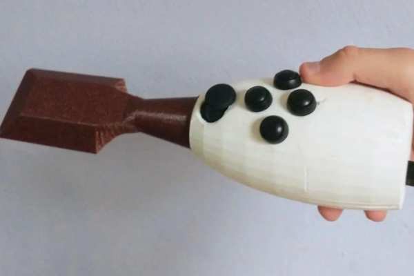
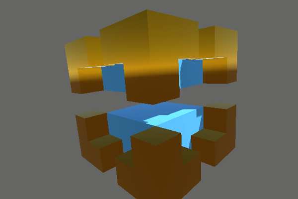
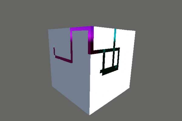
You can paint over a 5 x 5 x 5 cube and chip away cubes you don’t need, to create a miniature sculpture of whatever you’d like! You can even add colour to your creations.
I found the idea of linking Arduino with Unity interesting, as it’d mean that I could, in essence, make a custom game controller, which could even be controlled by things not usually seen in game controllers, like light, temperature, or distance to another object.
I decided to use an accelerometer to let physical player input have an effect inside of a digital game. By ‘chiselling’ with the chisel, you can remove parts of the larger 5 x 5 x 5 cube, like an actual chisel!
You can see a video of it in action here (Google Drive).
I will go more in-depth into my process in the final steps (this is a student project) – I’d rather not bloat this introduction.
Supplies
Although you can use other, similar components, I do recommend using these since the measurements of the 3D prints are quite precise!
Materials and Components
- 1 Arduino Uno Rev3
- 1 USB 2.0 Cable Type A/B
- 1 Joystick (or 0 if just using buttons)
- 4 2-pin Buttons (5 if just using buttons)
- 18 Male-Male Jumper Cables (or 15 if just using buttons) (preferably around 10 cm)
- 1 ADXL345 Accelerometer
- 2 Cable Lugs, (one male, one female, one to fit 4 cables, one to fit 1 cable)
- Approximately 55 meters of 3D filament (2 mm layer height, 10% infill)
- Solder
- Sanding Paper (recommended)
Tools
- Cable Lug Crimping Tool
- 3D Printer
- Soldering Iron
- Sander (recommended)
- Liquid Glue (might also work with a regular glue stick, but I didn’t feel like going through that suffering)
Digital Components
- 3D-Printing software like Ultimaker Cura
- Arduino IDE
- Corresponding files on my GitHub project
- Download the STLs of the 3D-printables in ‘3D Print STLs’.
- Download the corresponding Arduino code in, well, ‘Arduino Code’.
- ‘CubeColor’ if using a joystick, ‘CubeColorNoJoystick’ if not using a joystick.
- Download the ‘Build’ folder. Execute the Soft Squares.exe to play.
- If you want, you can also download the ‘Source’ folder, which contains the Unity project I made.
Step 1: 3D Printing
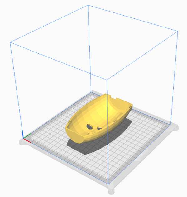
In order to assemble the chisel, you’ll need to 3D print the various components from the downloaded STLs. How you’ll print depends on your 3D printer and 3D printing software, but 2 mm layer height with 10% infill worked fine for me (well, minus all the failed prints – but I don’t believe that’s because of those settings).
I recommend starting with printing the Chisel Top, then Joystick Support, then Joystick Support 2, and then Chisel Bottom and Chisel Front – most of the shenanigans will be happening at the top part and will involve the joystick supports, so if you want to be time-efficient you can print those and work on the next few steps whilst printing the bottom and front part.
Step 2: Sanding
To make the chisel comfortable to hold, I recommend sanding some of the 3D prints.
- You should mainly sand the exteriors of the top and bottom of the chisel, and the front part of the chisel if you feel like it.
- Be careful with the holes at the top!
- You might also need to sand the extrusions on the bottom part – check if you can slot the top and the bottom part into each other!
- You won’t see the supports in the end result and they’re made to be placed inside of the chisel, so don’t sand those.
- Avoid sanding the front of the top and bottom part of the chisel, or the bottom of the front part of the chisel (… that’s a sentence). We’ll be glueing the parts together there, so it’ll help if it’s just a straight, flat surface.
Step 3: The Buttons
(note that the image with the soldering was later scrapped – just used for clarity)
Once you have printed the top, you can start messing with the buttons! Hooray.
The buttons will be used to control the colour and to move the cursor in-game, as well as move the camera if you’re just using buttons.
If printed successfully, the top part will feature 5 holes – 1 larger one (for a joystick) and 4 smaller ones – these 4 smaller ones are for the buttons. We’re going to install the buttons and get them wired up.
Note that you can also wire the buttons first – this was easier for me, personally.
If you’ve got the same buttons as me, this should be fairly simple.
- The buttons feature a thin nut and washer, which you can screw off just using your hands.
- Now, the bottom part of the button should be able to fit through one of the holes. So, uh, get it in there!
- Then, re-screw the nut onto the bottom part of the button to get it secured in the hole (see the images). Sadly, the washer probably won’t fit – but this shouldn’t be a problem, so dispose of it.
- Repeat this until all four buttons are installed.
Since we’re using two-pin buttons, we only need two wires per button, one to go to the ground, and another to go to one of the Arduino’s digital pins.
- Fit a wire through one of the pins, which will go to the ground. Make sure it’s secured by either twisting the end or soldering it.
- Fit another wire through the other pin, which will later lead to one of the Arduino’s digital pins.
- Repeat this until all four buttons have two wires.
Connecting the ground wires
As the Arduino only has three ground pins, we’ll need to connect the ground wires together so that they can share a single ground pin.
- Gather the four ground wires into the larger cable lug.
- You might need to strip the wires first in order to make sure they reach in there – if you run into any issues later, this could be a problem.
- Using the crimping tool, press the cable lug until the wires are stuck in there firmly.
- Gather a single wire into the other, smaller cable lug.
- Using the crimping tool, press the cable lug until the wire is stuck in there firmly.
- Connect the two cable lugs to form a four-in-one ground cable!
You can also do this by soldering as I tried in one of the images – but this was quite inconvenient and caused some issues with the limited amount of space inside of the chisel.
Securing the cable lugs
One issue I frequently encountered whilst testing was that the metal of the cable lug would touch other Arduino components, causing it to function incorrectly (one time even thinking I was ‘connecting an unknown device’ – I’m not sure whether I should be alive, honestly). So, we’re going to limit how much wiggle room the cable lugs have.
- Place the cable lugs above the indent for the USB cable (see image).
- Glue the lugs securely so that they can no longer move.
That’s all! Buttons installed.
Step 4: The Joystick
Now, we can mess with the joystick!
The joystick will be used to move the camera in-game. It’ll also be used as a button to change between the various modes in the game.
The joystick belongs to the larger, remaining hole in the top part of the chisel. Keep in mind that you will need the joystick supports – if those are still printing, you could skip to step 4 for now and return once the supports are done.
Wiring the joystick
- For each pin, connect a wire to it, by twisting around it or soldering it (or any other way you see fit).
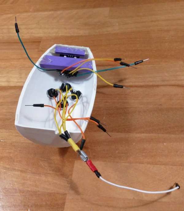
- I highly recommend using different-coloured wires! Later on, it’ll be difficult to see which pin is which, so having a colour code could majorly help with avoiding trouble later (trust me, I’ve been through it – see the first image).
Installing the first joystick support
To make sure the joystick won’t fall, we’re going to add some 3D printed supports, starting with the support which looks like a rejected Lego stud. The holes on the corners of the joystick should fit in there just right.
- Place the support at the front of the top part (where you’ll also find the larger hole). Move it to the bottom of the part, so it’s level with where the part ends (see image).
- Glue the support and make sure it’s stuck.
- You might need to ‘extend’ the support with some extra glue like I had to so that the joystick will fit correctly. Whoops.
- Be careful not to have glue spill on the rim of the top part. You might’ve noticed the small holes on the 3D print – those will slot into extrusions on the 3D print of the bottom part. Spilt glue might mess with them slotting in.
- After letting the glue dry, check if you can wedge the joystick in and if you can move it sufficiently – if so, congrats! If not, try glueing the support again.
- If you’re having trouble, just glueing the support with the joystick already on it could help – but could also result in it getting permanently stuck (don’t worry, it’ll get permanently stuck soon – but might not be a good idea at the moment if you need to make changes after it already got stuck).
Installing the second joystick support
You might’ve noticed when testing the first joystick support, that attempting to press the joystick down feels unstable – so we’re going to install the second joystick support!
- Make sure the wires are secure and that the joystick is already attached to the first support – the joystick will be stuck after the attachment of this support, so be prepared for that.
- Place the support at the same level as the first support. The second support should cover the other holes of the joystick but should leave the pins exposed.
- You might need to turn over the support if you’re having trouble getting it to fit – it has a slight slant to it.
- Glue the support and make sure it’s stuck.
- Again, glue on the rim could cause future problems.
- After letting the glue dry, press the joystick and see if the support provides resistance – when you actually press the button, you should hear a faint click. If this doesn’t work, try glueing the support again.
Congrats, the joystick is secure!
Step 5: The Accelerometer
In order to track if the chisel is chiselling away, we’ll be using an accelerometer to track the speed of the chisel. This way, we can break a cube in-game if the chisel moves fast enough.
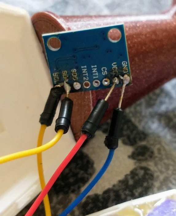
Soldering the accelerometer
For the GND, VCC, SDA and SCL pins, connect a wire to it, by twisting the wire, soldering, or any other way. Be sure that the wires don’t touch each other or connect with other pins (especially when using solder)!
Slotting the accelerometer
To avoid the accelerometer from going all over the place, the bottom part of the chisel has a neat slot where the accelerometer can fit! So, uh, make sure it’s in there.
Step 6: Assembly
Now that we’ve got all the parts ready, we should be able to assemble the chisel! Just a few more steps.
Glueing the front to the bottom
To make the chisel more… chisel-y, we’ll glue the front part to the bottom part. That way, when you slot in the top part, it’ll look like an actual chisel! (…with some imagination, that is)
- Only glue the bottom half of the chisel!
- For me, it helped to hold the bottom and front parts upright and glue them together like that.
- Once again, make sure to not spill glue over the rim!
- After it has dried, check if the front actually sticks when slotting the top on the bottom.
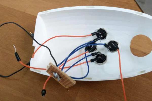
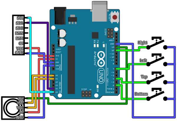
The wiring
Now, it’s time to get all the wires in there – place the Arduino Uno on the elevated part of the bottom (so that the USB cable can fit through the indent) and see the provided wiring diagram to see how to get the wires in order.
- Make sure the accelerometer is attached to 3.3V, 5V won’t work and might damage it.
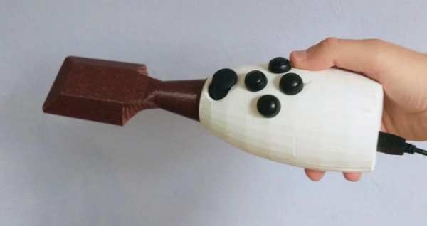
The result
Now, place the top on the bottom and see your finished product! …nearly, that is.
- Admittedly, you might need to push your wires in there a little, especially if you’re working with longer wires.
Playing the game
Connect the Arduino to a computer with the Arduino IDE using the USB cable, funnelling the cable through the hole at the back of the chisel. Upload the corresponding code to the Arduino depending on whether you want to use your buttons to move the camera, or if you want to use your joystick instead (I put the code below here for easy access, but it’s also on GitHub in the ‘Supplies’ section).
If you want to know what the code does exactly, I put comments in there, but in essence, it checks whether a button was pressed or lifted this frame, and sends that information to Unity (I could also send the state of every button every frame, but I’ve discovered that Unity doesn’t like that).
Then, execute the game and play! Keep in mind the chisel needs to be plugged in in order to work.
Step 7: Controls
Here’s a simple overview of the controls and how the game works.
There are four modes:
- Colour – change the properties of what you’re painting with.
- Move – move the cursor over the big cube.
- Paint – move the cursor over the big cube, as well as painting the surface that the cursor is on.
- View – move the camera using the buttons.
Joystick – Move the camera (if using ‘CubeColor’), and press to switch between modes.
Buttons – Move the cursor (Move and Paint), move the camera (View), switch between what property you target (Color, left and right) or change the value of that property (Color, up and down).
Swing – Swing the chisel to delete the cube the cursor is currently on.
S-key on the keyboard – Take a screenshot of what you made! Should be saved in the same folder as the .exe file.
Congrats! You’re now done with the project. Below are some ‘extra’ steps featuring failed attempts, other ideas I had at first, and other nonsense.
Step 8: Process
I made various amounts of concepts in Unity to see what I would like best, but I only decided to make the chisel in the end.
At first, I wanted to do something with light in Unity. You’d have to stay in shadow to survive. Being in light would hurt you, which would be indicated by dimming lights. I did manage to make this, in the end, but it didn’t feel exciting and was just Arduino being used as a regular controller without much flair to it.
Afterwards, I tried making something like Flappy Bird in Arduino, using a pressure sensor to apply force to the bird. This did already feel better, as it made use of something unusual in game controllers like a pressure sensor. Still, however, it felt a bit bland.
I then imagined some crazy concept where, using Bluetooth, Arduino would connect to your phone, after which it would control a Unity game on your phone, and you’d use the Arduino as a controller whilst the phone was inserted into a VR-headset-esque device. You’d play as a bird flying around in an open world.
…although I do tend to take on overly-ambitious ideas, I recognized that this was far too much for the time I had left, so, I just started brainstorming random ideas.
At first, I had the idea of being able to color your own cube (hence why the Arduino code is called ‘Color Your Cube’), and depending on the color, it’d have different stats. Testing out coloring the cube was neat – so then I tested it where your cube character would consist of multiple cubes (on a 2D plane) – and then I realized I just made an art program.
I wanted to expand on this idea, so then I thought of deleting pixels – which lead to me wanting to create a chisel which could chip away at blocks using motion. At first, I wanted to use a distance sensor to use movement, since I already had a distance sensor, but in the end, I decided to go for an accelerometer – I had to buy new electronics anyway, so I opted for an accelerometer, which would probably detect movement more accurately (with the distance sensor, you could also face the chisel to another location to ‘chisel’).
Lastly, to really make it like you’re using a chisel, and not just a brush, I extended the 2D plane of cubes into 3D, so it’d feel like you were making a painted sculpture. And, well, that’s what I ended up with!
Source: Soft Squares – Chisel Away With Arduino in Unity
- How does the chisel remove cubes in the game?
The ADXL345 accelerometer tracks the speed of the chisel; swinging it fast enough breaks a cube in-game. - Can I use the chisel without a joystick?
Yes, you can use just the four buttons to move the cursor, move the camera, and switch properties. - What voltage should the accelerometer be connected to?
The accelerometer must be attached to 3.3V, as connecting it to 5V might damage it. - How do I change colors in the game?
You use the buttons to switch between properties like Color, then use specific button combinations to change the value. - Does the project require 3D printing software?
Yes, you need software like Ultimaker Cura to prepare the downloaded STL files for printing. - What is the recommended layer height for printing the parts?
A 2 mm layer height with 10% infill worked fine for the author. - How many ground pins are available on the Arduino?
The Arduino only has three ground pins, so the four ground wires from the buttons must be combined using cable lugs. - Which key takes a screenshot in the game?
Pressing the S-key on the keyboard saves a screenshot of your creation. - Why did the author choose an accelerometer over a distance sensor?
The accelerometer detects movement more accurately, whereas a distance sensor could be tricked by facing the chisel at another location.