In one of the previous instructable, we saw how to make a simple thermometer with ATTINY 85 which can last for 140days with a single battery and it still works great after 40+ days with the same battery I showed in the video.
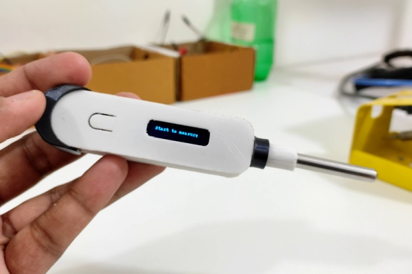
But it was a tiny bit clumsy when it came to the electronics and the programming. So, in this instructable, let me show you how to make a thermometer on steroids with features nobody asked for, but by doing so I hope you will definitely learn plenty of electronics along the way.
The device will have the following features:
- Realtime reading using WebSockets
- Auto sleep on when not in use
- Control the thermometer from a webpage
- Sleek PCB design
- Integrated esp-01F programmer
- Integrated lipo charging circuit
- 3d printed case
Supplies
These are the list of products that can help you do this project with ease
(Affiliate Link)
- ESP-01F : https://amzn.to/3imkkd5
- SMD Resistor : https://amzn.to/3Bhy0yQ
- SMD Capacitor : https://amzn.to/3Betykm
- BC817 transistor : https://amzn.to/3kuOcGN
- CP2102 IC : https://amzn.to/3z8GW7F
- TP4056 IC : https://amzn.to/3il5lQz
- SMD LED : https://amzn.to/3kuC0pz
- Voltage regulator : https://amzn.to/3ifM1Es
- Micro USB : https://amzn.to/3kumREM
- White PLA : https://amzn.to/3Betj8W
- PETG filament : https://amzn.to/3w6bB46
- DS18B20 : https://amzn.to/3ylGRy0
- OLED display : https://amzn.to/2VcEATc
- Resistor Kit : https://amzn.to/3frj4nx
- 3d Printer : https://amzn.to/3trVWKw
- Printer Upgrades : https://amzn.to/3hbK3Ga
Step 1: Why ESP-01F?
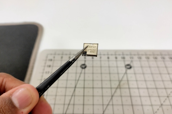
In version 1 the flash storage was very limited, hardly 8kb, I had struggled a bit for running different libraries. So, this time I chose the esp-01f, which comes with a 1MB of flash memory, which is 128times greater than the ATTINY 85. Along with this it also has features like WiFi, UART, higher clock speed up to 160MHz. Even though it won’t matter for this particular project we can flex the specs to make the thermometer look more muscular.
But it does come with a cost, the esp-01f is a very power-hungry module because of the onboard wifi connectivity, but this power consumption can be reduced greatly by putting the module to deep-sleep where it should consume just 20uA according to the datasheet.
Step 2: Other Components
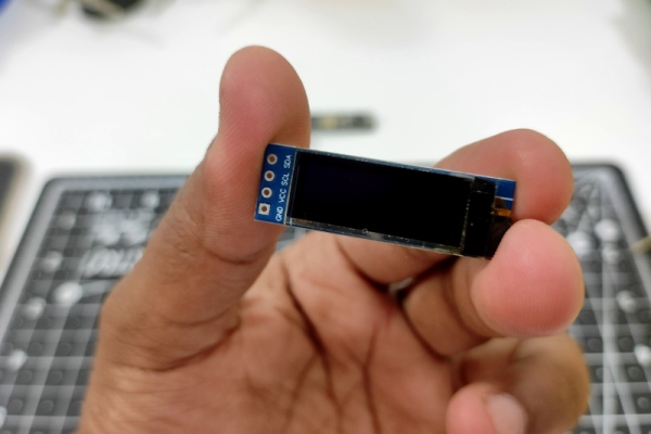
The other components are similar to the thermometer version 1. For the display, I’m going to use the same 0.91inch 128X32 OLED display, for the temperature sensor DS18B20 probe, and finally for the battery a small 150MAh lipo battery.
Everything looks easy to put together but with great power comes great responsibilities. There are so many smaller details that we are missing to complete this project at least to a bare minimum.
Step 3: Smaller Details
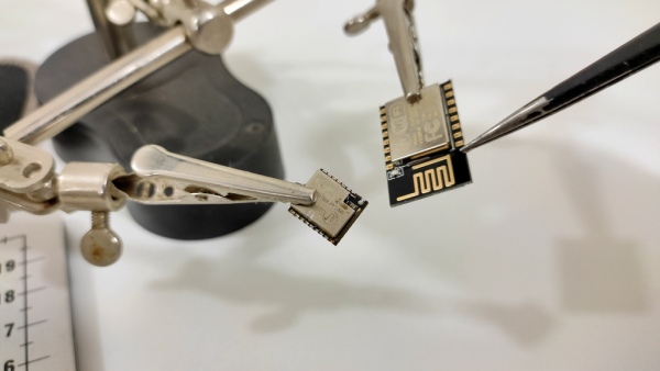
To begin with, the size of the esp-01f is so compact that there is no antenna built-in. So either we have to build one on the PCB or add an external one, if not there will be stability issues and a shorter range for wifi connectivity.
But I’m going to do neither of those because I haven’t found myself any true purpose of having wifi integrated with the thermometer yet maybe someday I will but until then I can manage without the antenna.
Anyway, apart from this programming this module is clumsy and super hard because of the tiny footprint and not being able to solder this on any perf board. So many of my previous methods and technique for programming would not work quite well with this.
Step 4: USB to Serial Convertor
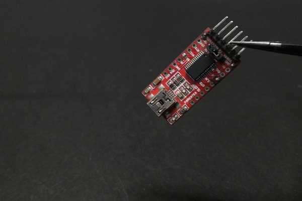
That’s the reason I plan to integrate a USB to serial converter to program the esp-01f. Just like the ones on the development boards like Arduino, Nodemcu, etc. So, technically if you could give more pinout to the thermometer it can be used as a development board, well that’s one of the reasons I said it was on steroids.
To implement the serial programmer there are plenty of options, we can use CH340 which would be the cheapest, mostly seen on Arduino clone, or FTDI which would be the most expensive one, which was previously used in the original Arduino development boards. But I’m going to use neither of them because their IC package is quite large and quite bigger than the wifi module itself.
Step 5: CP2102 USB to Serial
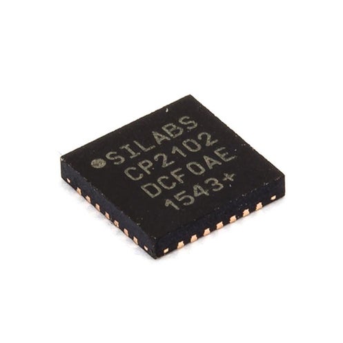
So, I chose the CP2012. Which is a USB to serial converter by silicon labs that is mostly used in the NodeMCU and the ESP32 development board and their pricing is pretty moderate compared to FTDI and also the size of the IC package is quite small which is perfect for our device.
Step 6: Charging Circuit
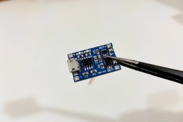
Finally, there is one issue, the Lithium polymer battery. Since it’s a rechargeable battery we need to have a provision to charge it. One way we could do this is by just taking the battery out and charge it, and slap it back on when it’s done. But it gets us back to the old problem again. Beginning clumsy and not elegant. So, we’ll add a tp4056 IC and a micro USB to have an onboard charging circuit.
Step 7: Printing PCBs With PCBWay
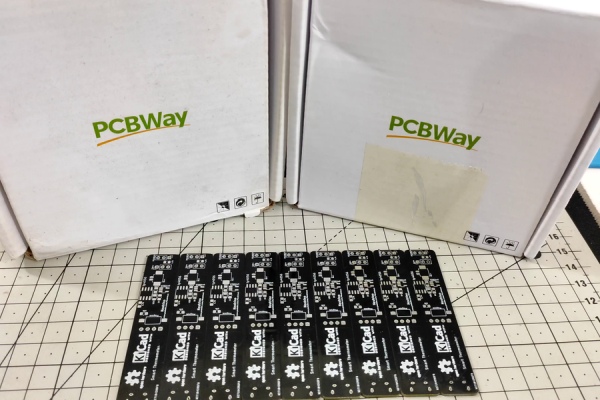
I sent the Gerber file for manufacturing with this project PCB sponsor PCBWay.
If you need custom PCBs for your project, they offer 10 custom PCBs for as low as 5$ and a variety of customization that you can choose for your PCB, like the color of the solder mask, silk layer, and surface finish. And on your first order, you get a coupon of 5$! So, basically, you will be just paying for your shipping during your first order. So check out the link in the description to visit their website.
Since now the PCB (Gerber) is ready. It’s time for soldering!
Step 8: Soldering!!
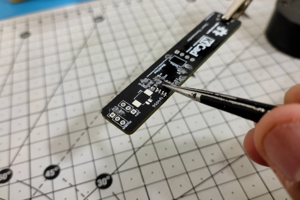
Everything worked great and looked good until I realized the mistake I made. The OLED display was facing the other way around. But the fix was pretty simple. I had to just solder the OLED with wires instead of the header pins.
From here on the circuit was sleek. Just plug in the micro USB and the charging circuit charges the battery and just by connecting this micro USB to a PC, you can program the esp-01f using Arduino IDE.
Step 9: Programming the Smart Thermometer
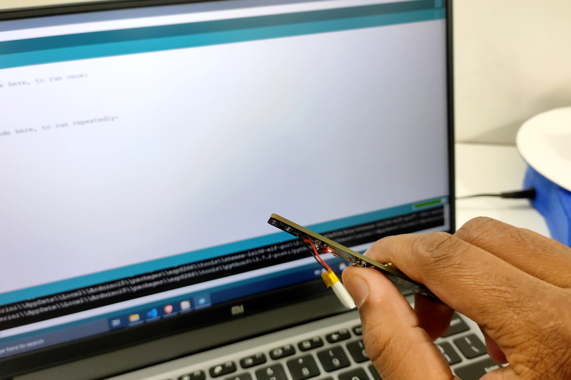
Programming is totally simple in this version. Just open the code (Github) “Thermometer V2.ino” in Arduino IDE and set up the Arduino IDE to upload code to the esp8285. When you press the upload button, the code should automatically flash the esp8285 with the latest code, but if it doesn’t, just click and hold the program button as shown in the first image during the upload process.
Step 10: Webpage
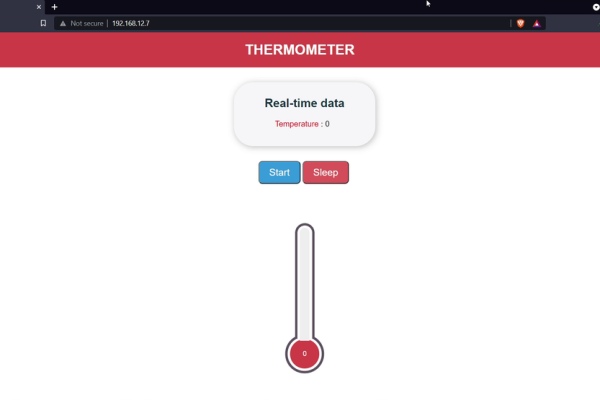
I kinda hate web development, but still anyway I managed to build a sloppy webpage with WebSockets to show some real-time temperature reading from the temperature sensor. It doesn’t use any fancy libraries or fancy frameworks. It’s written on HTML, CSS, and Vanilla Javascript (code).
Step 11: 3d Printing and Assembly!
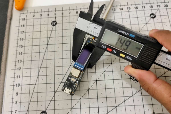
Since the board is ready, I wanted to build a funky case for the thermometer. I thought of making a smoking pipe, but unfortunately, I didn’t have the same idea when I was doing the PCB design. So it was quite difficult to build and was not that good looking so I had to ditch that idea.
Instead, I measured the exact dimension of the PCB and started designing a simple elegant case while still managing to have the same easy accessibility to the circuitry without any fasteners just like version 1.
Then the rest was just 3d printing and assembly!
3d printing
- Printer – Ender 3v2 (Cura slicer)
- Supports – Turned on
- Layer height – 0.2mm
- Filament – PLA+
- Nozzle Temperature – 210c
- Nozzle Heat bed – 72c
Step 12: Testing the Smart Thermometer
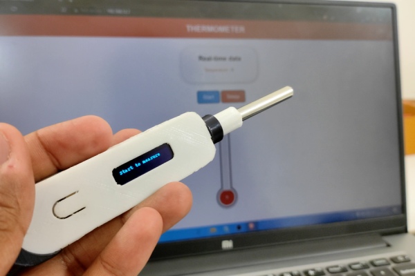
Let me quickly walk you through how it works.
Just click on the top button, this will reset the esp and wake it up from sleep mode. Once the device is active it will turn on an access point where we can connect. After connection opens any web browser and searches for the IP address assigned in the code or by searching “http://temperature.local“. That’s it now we can measure the temperature by clicking the start and see the real-time data on the webpage.
You can also put the thermometer to sleep by click on the sleep button. Which would clear the display and put the thermometer to deep sleep.
If the device is turned on for more than a minute and nobody made the connection to the webpage the device will go to deep sleep automatically to save power.
Step 13: Power Consumption
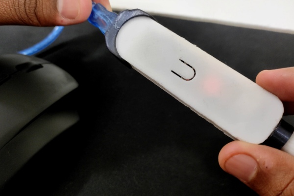
As I told you at the start of the instructable, the power consumption going to be higher than version 1, because of the ESP-01F. So, if you see the multimeter reading when the Access point is turned on and a client has connected, the power consumption is around 93mA. When the thermometer is in deep sleep it consumes around 1.8mA which is quite significant when compared to the previous version where it consumed under 60uA.
Considering the ESP-01F consuming around 20uA (from the datasheet), the total circuit should still consume less than 100uA. The reason why it consumes 1.8mA is because of the other features we added like the charging circuit and the onboard CP2102 USB to Serial programmer.
Step 14: Final Thoughts!
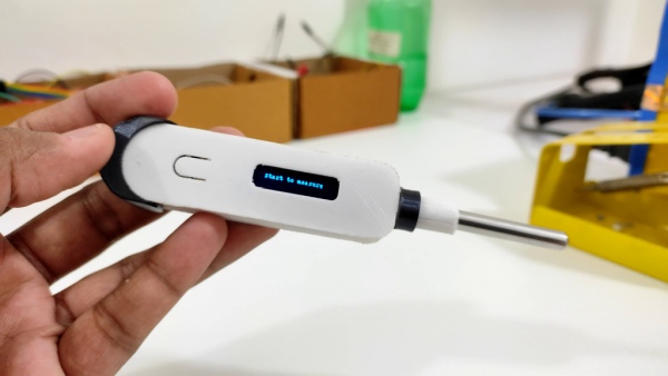
This device doesn’t have much value when compared to the existing thermometer, but building a device with all the user-friendly interfaces like the buttons and onboard programmer is quite challenging for beginners and even for some intermediate learners. I hope at least this instructable gave you few ideas about building a bit more sophisticated project and how to approach it.
So, if you like the video make sure to hit the like button and be subscribe to watch more upcoming videos. And I promise I will definitely come up with something better than a thermometer. Until then you can watch my other video from the link on the screen or the link in the description.
Source: Smart Thermometer Using Esp-01F and Web Socket [Arduino IDE]
