Summary of Smart Phone Controlled FM Radio using Arduino and Processing
This project converts a non-functional manual FM radio into a smart wireless device controllable via an Android app. Using an Arduino Mega and an HC-05 Bluetooth module, the system reverse-engineers the original button signals to generate variable voltages (0–1.7V) through PWM and an RC low-pass filter. A custom Processing application communicates with the microcontroller over Bluetooth, allowing users to control the radio remotely or automate functions like wake-up alarms.
Parts used in the Smart Wireless FM Radio:
- Old or unused FM radio
- Arduino Mega
- HC-05 Bluetooth module
- Resistors
- Capacitor
- Transistor resistor network (optional)
- Digital potentiometer (optional)
- Dot board for circuit assembly
- Connecting wires (Black, Blue, Green)
- Android smartphone
In this project we will use an existing FM radio which went repair a long time ago, to convert it into a Smart Wireless FM Radio controlled using Phone, with the help of Arduino and Processing.
We can convert any manually operated electronic device into a Smart Device using the same procedure. Every electronic device operates with the help of signals. These signals might be in terms of voltages or currents. The signals can either be triggered manually with the help of user interaction directly or with the help of a wireless device.

By the end of this project we will be able to convert most of our common electronic devices, like a Radio which works on buttons, into a Smart Wireless Gadget which can be controlled by Smart phone over Bluetooth. To achieve this we will have to do two main things.
1. Predict how the signals are generated in the existing mechanical button system.
2. Find out a way to trigger the same signal with help of a small add-on circuit.
So, Let’s get started…
Components Required:
For this project an old or unused electronic device like a radio, TV, CD player, or Home theatre can be selected. The actual components might vary based on the device you select. But to make it wireless we would need a microcontroller which is an Arduino here and a wireless medium which is a HC-05 Bluetooth module.
Reverse Engineering:
Okay, so now I have selected an old FM radio player which stopped working a long time ago. And when I opened it I found that the buttons on it have stopped working. This will be a perfect device for us to work because we won’t need the buttons anymore as we are going to make it wireless completely. The below picture shows the Radio which I opened.
This was the button setup of my radio (above picture). As you can see there are eight buttons from which the radio takes input. You can also notice that there are eight resistors on the board. What can you conclude from this…? Yes each resister is connected to a switch. Now let’s take a look on the back side of the board:
You can trace out the connection with the help of the PCB tracks, but if you are still confused you can use your millimetre in connectivity more and figure out the circuit. This board has three terminals (circled in red) which gives signals to the main FM radio board. These pins were marked as S1, S2, and 1.7V. This means that constant voltage of 1.7 Volts is sent form the main board to this board and as the user presses any button, there will be a voltage drop across the corresponding resistor and through the pins S1 and S2 a variable voltage will be sent back. This is how most of the buttons in our electronic devices work. Now since we have figured out how it worked, let’s make it wireless.
Working Explanation:
So now to make it wireless we just have to give a voltage between 0 – 1.7V across the S1 and ground out the main board. There are few ways, using which you can mimic these button setup using a microcontroller.
We can use a Digital potentiometer and make it provide the resistance on the board as programmed and when required. But this will make things complicated and costly as working with Digipot requires SPI and Digipots are costly.
We can also use a transistor resistor network in which each resistor of different values are activated by a transistor which in turn is controlled by the microcontroller itself. But again to do this for eight buttons the circuit will get complicated.
The simple way of doing this is to directly generate the required variable voltage from the microcontroller and feed it to the signal pins. Sadly, Arduino only has ADC and doesn’t have a DAC. But, luckily we have PWM in Arduino. This PWM can be made to act as a variable voltage with the help of a simple RC Low Pass Filter.
A low pass filter is shown above, the key component here is the capacitor which will ground the entire pulsating signal and a pure DC is sent as output. So the PWM signals from the Arduino have to be sent through a low pass filter and then given to the signal board of the FM radio.
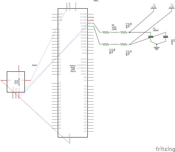
The circuit is easy to build on a dot board as shown above. Here the Black wire is for ground and the Blue and Green wires on the left will be sent to our FM boards S1(Green) and S2(blue), and the wires to the right will receive PWM signals from Arduino’s Pin 9 & 10 (see picture above) and pass to the FM board via a Low pass filter. The Bluetooth module uses pins 11 and 12 as Rx and TX.
Now we can generate PWM signals from 0 volt to 1.7 volt and find out how our Radio behaves for different voltage levels. The next step is to make this thing wireless.
Circuit Connections:
This schematic shows the entire setup of Low Pass Filter and HC-05 Bluetooth Module connected to Arduino Mega for Bluetooth Controlled FM Radio.
Arduino Program:
Program for the Arduino is given in the Code section below. You can also test the Variable Voltage range for your electronic device by using this program here.
Before we start with building our own Android App for our Radio it is advisable to test the wireless feature with help of a Terminal Bluetooth Monitor App as shown in Video below. Check this Article to configuring Bluetooth Terminal App on Arduino. Once we are confident with its working, we can jump into making our own Android app.
Using Processing to Make Android App:
It is cool to make our device wireless, but we can also add some personal touch to our device by creating our own Android app. We can control the device on automatic scheduled times or control it based on your wake up alarms. You can even make your radio play your favourite channel when you get home. Imagination is your limit here. But for now we will create a simple user interface using processing, this app will only have few buttons using which you can control your FM radio.
Processing is open source software which is used by artists for Graphics designing. This software is used to develop software and Android applications.
The Processing Code for the Android App to control this Wireless FM Radio is given here:
First we built this app on PC in JAVA mode, to test it properly, here is the Processing Code for the same. Right click on it and click on ‘Save link as..’ to download the code file. Then open the file in ‘Processing’ software and click on ‘Run’ button to check how it will look in the Phone. You need to install ‘Processing’ software to open *.pde files.
Once we have tested out App in JAVA mode we can easily convert it into Android Mode by changing to Android tab on the top right corner of the Processing window. In order to make our Android Phone turn on its Bluetooth and connect to our HC-05 module automatically, we need to add the following codes to our existing Java program to make it an Android App. We have already provided the full Android Code in above link, so you can directly use it.
Below are some Header files to enable Bluetooth functions:
import android.content.Intent;
import android.os.Bundle;
import ketai.net.bluetooth.*;
import ketai.ui.*;
import ketai.net.*;
import android.bluetooth.BluetoothAdapter;
import android.view.KeyEvent;
Below lines communicates with our phones Bluetooth adapter using Ketai library and we name our adapter as bt.
BluetoothAdapter bluetooth = BluetoothAdapter.getDefaultAdapter();
KetaiBluetooth bt;
Below part of the code will trigger a request to the user asking them to Turn on the Bluetooth on app start up.
//To start BT on start*********
void onCreate(Bundle savedInstanceState) {
 super.onCreate(savedInstanceState);
 bt = new KetaiBluetooth(this);
}
void onActivityResult(int requestCode, int resultCode, Intent data) {
  bt.onActivityResult(requestCode, resultCode, data);
}
//**********
Here we instruct our Android App to which Bluetooth device we have to get connected with. The line bt.connectToDeviceByName(selection); expect a device name from our setup function. Since our Bluetooth device is named as ‘HC-05’, below line is added in the setup. This name will differ based on your Bluetooth modules name.
//To select bluetooth device**********
void onKetaiListSelection(KetaiList klist)
{
 String selection = klist.getSelection();
 bt.connectToDeviceByName(selection);
 //dispose of list for now
 klist = null;
}
//**********
bt.connectToDeviceByName("HC-05");
Either you can do these changes in Processing Code for PC (Java mode) or can directly use our Android Processing code given in above link. Then directly connect your phone to your laptop using the data cable and enable USB debugging on your phone. Now click on the Play button on the processing window in PC, the application will be directly installed on your Android Phone and will be launched automatically. It’s that easy, so go ahead and try it out.
The below picture represents our Android Application UI along with its coding window. Check out the Video to understand and run the Code in Android Phone as well as in computer.
Read more: Smart Phone Controlled FM Radio using Arduino and Processing
- How can I convert a manual electronic device into a smart gadget?
You must predict how signals are generated by the mechanical buttons and find a way to trigger the same signal using a small add-on circuit. - What is the best way to mimic the button setup using a microcontroller?
The simple way is to directly generate the required variable voltage from the microcontroller using PWM and a Low Pass Filter. - Why did the author choose not to use a digital potentiometer?
A digital potentiometer makes things complicated and costly because it requires SPI communication and the components are expensive. - Can I use a transistor resistor network for this project?
Yes, but using a transistor resistor network for eight buttons will make the circuit complicated. - How does the Arduino generate variable voltage since it lacks a DAC?
The Arduino uses PWM signals which act as variable voltage when passed through a simple RC Low Pass Filter that grounds the pulsating signal. - Which pins on the Arduino are used for the Bluetooth module?
The Bluetooth module uses pins 11 and 12 as Rx and TX on the Arduino Mega. - What software is used to create the Android application interface?
Processing, an open-source software used for graphics designing and developing Android applications, is used to create the user interface. - How do I connect my phone to the Bluetooth module automatically?
You need to add specific code using the Ketai library to request turning on Bluetooth and instruct the app to connect to the device named 'HC-05'.