Summary of Circuit Fun: Control an RC Servo with an adjustable DC voltage
This video demonstrates a circuit converting analog voltage to PWM signals for RC servo control. It utilizes rail-to-rail op amps, resistors, and capacitors to create an integrator, hysteresis comparator, and DC signal conditioner featuring an attenuator, inverting amplifier, and level shifter. The design allows precise servo positioning via adjustable DC input rather than standard pulse width modulation.
Parts used in the RC Servo Control Circuit:
- Rail-to-rail op amps
- Resistors
- Capacitors
- Integrator
- Hysteresis comparator
- DC signal conditioner
- Attenuator
- Inverting amplifier
- Level shifter
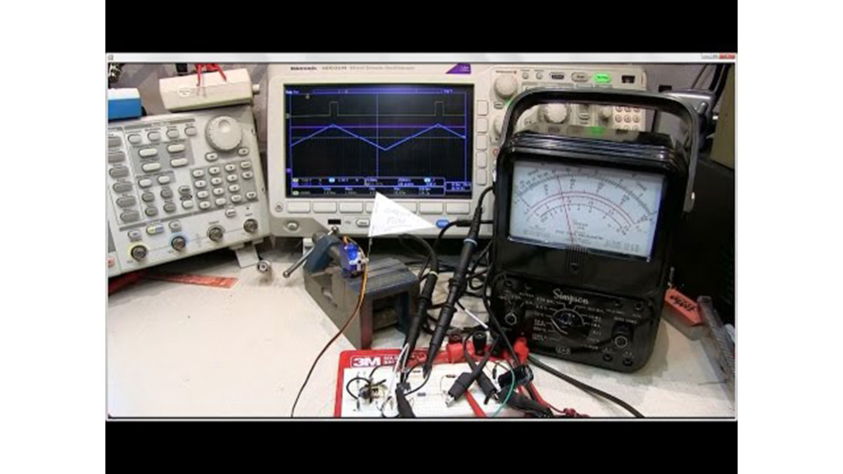
This video shows a simple circuit that can be used to control the position of an typical remote control (RC) style servo with an analog voltage. The PWM (pulse width modulated) control signal format for an RC servo is reviewed, followed by the presentation of a simple circuit that can be used to control the servo with a simple adjustable DC voltage.
The circuit is built with rail-to-rail op amps and a few resistors and capacitors. Note that the schematic presented doesn’t include all of the decoupling on the power supply and reference lines that you would likely want to include. A description of the circuit, as well as a more in depth discussion of each of the building blocks such as an integrator, hysteresis comparator and DC signal conditioner circuit including an attenuator, inverting amplifier and level shifter, is presented.
For more detail: Circuit Fun: Control an RC Servo with an adjustable DC voltage
- What is the primary function of this circuit?
The circuit controls the position of an RC style servo using an analog voltage. - How does the circuit convert the input signal?
It converts a simple adjustable DC voltage into a PWM control signal format. - Which components are used to build the circuit?
The circuit is built with rail-to-rail op amps, resistors, and capacitors. - Does the schematic include all power supply decoupling?
No, the presented schematic does not include all decoupling on the power supply and reference lines. - What building blocks are discussed in the article?
The article discusses an integrator, hysteresis comparator, and DC signal conditioner. - What specific functions are included in the DC signal conditioner?
The conditioner includes an attenuator, inverting amplifier, and level shifter. - Can this circuit be used with typical remote control servos?
Yes, it is designed to control the position of a typical RC style servo. - What type of voltage controls the servo in this setup?
An adjustable DC voltage is used to control the servo position.