This board needs FTDI cable to program it.
It is not Arduino compatible in the meaning of taking shields (just like every small form factor board isn’t).
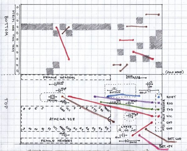
But it has all the same pins (exept 3.3V power and Vin*) available as female headers. The input and output pins that are right next to each other on original Arduino, almost are the same here, except digital 4 and 5. That means the order is:
RESET	0	1	2	3	4	VCC	GND	_	_	5	6	7	8
9	10	11	12	13	VCC	AREF	GND	A0	A1	A2	A3	A4	A5
It has power indication LED. Not an essential part, but it reminds you to remove the battery when not in use and I have also found it to be useful to notice shorts in my circuit – the power LED goes dim in that case.
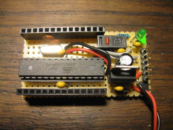
* – Mine has only 9V battery clip directly soldered to it, but this is the easiest part to modify. It also does not have ICSP header, but in the rare case a ISP programmer would be needed it is possible to access all these pins through female headers or remove the Atmega from socket.
So what’s the purpose of such thing? I felt I needed a secondary controller besides my usual Arduino for testing things out. I missed that when programming my robot for a contest where IR transmitters were supposed to indicate important places and my attempt to make ATtinys do similar transmission failed. And now I have a task of learning about radio modules ahead of me and I want a familiar platform to test them out before trying to also mess with microcontrollers new to me that are supposed to go into the final product.
When considering the price remember these aspects:
- Do you already have FTDI cable or for how much can you purchase it? (I managed to make one myself, but it takes precise etching and SMD soldering. Also the needed chip is not super cheap for experimentation. Further details http://www.instructables.com/id/FTDI-cable/ )
- Do you have an Arduino (in working order) or AVR programmer to use for burning bootloader on a blank ATmega or can you get the controller with bootloader for reasonable price?
If all that described suits you and you feel ready to do some tightly packed soldering – it really wasn’t too easy to get all wires to their right spot – then here is my documentation of the project
Step 1: Gather stuff
Skills prerequisites:
Medium level of experience in soldering – this is really tight packed project and it’s going to be really hard to fix cold or too messy joints in there.
Some understanding of electronics circuits and schematics preferred. You should be able to check the connections, firstly because it is really easy to make some mistakes in a circuit of this complexity level and secondly because I made the final drawing only after finishing my job and fixing couple of mistakes in it which means actually no one has yet made it „following the schematic“ and I might have passed a mistake in even though I did my best not to. Let me know if you find anything suspicious.
Materials:
- ATmega328 or 168. With bootloader (or a working Arduino or AVR programmer to use for burning it)
- Stripboard – piece of 11 x 22 holes where strips run parallel to the shorter edge, but see note about the button type.
- 7805 voltage regulator
- 16MHz crystal oscillator
- Pushbutton („mouse type“) – used as reset button, see images what the „mouse type“ means. You could use the regular round pushbutton in square housing, but it’s footprint is wider and then you must make the stripboard wider by one or even two holes. Mouse button saves room here. If you have a broken mouse form recent decade, they actually can be found in there usually.
- 28 pin socket for the ATmega
- Female headers – 2 x 14 or 14 + 8 + 4
- Male headers – 6 pc. For FTDI cable connector.
- 2 x 22pF capacitors (ceramic) – for the crystal
- 4 x 10nF capacitors (ceramic)
- 100nF capacitor (ceramic)
- 100uF electrolytic capacitor (rated 16V or more)
- 1 Kohm resistor – for reset pullup, 1/8 W is best size for my perfoboard schematic.
- ~330 ohm resistor – for the power indicator LED, can be other resistance value suitable for the LED, should be ¼ W, because there will be some power dissipation.
- Rectifier diode – to protect against accidental reverse voltage. These can be found in all kinds of old power supplies – computer PSU, phone charger etc.
- 9V battery clip – can be made form old 9V battery, but be careful while disassembling the metal outer part, I always manage to hurt myself in that process.
- Wires – any insulated wire thin enough to fit through stripboard holes.
- Paper and glue or sticker paper – for pin labels
- Duct tape, double sided tape, cardboard – for protecting the bottom side.Major Components in Project2 x 22pF capacitors4 x 10nF capacitors00nF capacitorLED, should be ¼ 9V battery clip
For more detail: Small form factor DIY Arduino on stripboard