I hope you will find this Instructable interesting and useful. It is only three (3) steps long, plus an introduction.
If you do find this article helpful, even if it is relative to when you see it some months or years old, please be kind enough to mouse click “Favorited” at the top of this Instructable. Your support is appreciated.
This Instructable uses only inexpensive components (except for the video of Sparki, and Sparki is not required), and it presents knowledge that will allow you to wirelessly control devices with any Infrared (IR) remote.
You may, and probably do, have an IR remote(s) from a no longer used TV, Roku, or other device(s) such as a stereo player, space heater, ceiling fan, string lighting, etc. It may at first seem as if this (these) older remote(s) is/are no longer of use, but this Instructable shows you a way to usefully repurpose it/them.
Alternatively, you can purchase an IR remote from China, as part of a kit (see below).
To successfully use any IR remote, one must first find the values generated by their IR transmissions, when the remote’s buttons are pressed. The second (2nd) Step, of this Instructable, provides a Sketch to find those numerical value(s) for any key(s) on your remote control, and what it/they represent(s) in IR code.
The last Step shows you how to use that information to control any component that can be controlled.
Thus, after two (2) simple Steps you will be able to use any IR remote(s).
That is, all you need to do to use an IR remote to wirelessly control a device is to: (1) find the value(s) of any key(s) you press on it, and (2) use this value(s) to control any device(s) you want.
This Instructable shows you one way to do this in Steps two (2) and three (3).
After you have studied this Instructable, you should be able to use any infrared (IR) remote to wirelessly control any controllable component.
There are many ways for Makers to wirelessly control components: RF, Bluetooth, Bluetooth LE, Wi-Fi, IR, etc, Of these, IR is the easiest to implement. Its major drawback is that it requires “line-of-sight”. Fortunately, for most microcontroller projects, this is not an issue.
The concept behind wireless IR remote control is very easy to understand and its use is also easy. Thus, it is surprising it is not used in more Maker projects. Hopefully, this Instructable can help mitigate that situation.
Infrared, sometimes called IR, is light that is just below the visual spectrum.
In fact, IR is part of the electromagnetic radiation (EMR) spectrum, and it has wavelengths longer than those of light we can see.
Much of the thermal radiation sent out from heated objects is IR.
Many IR systems, for Makers using Arduino or other microcontroller boards, come in inexpensive kits, which include a receiver, transmitter, and Dupont hookup cables. One such kit is shown in an attached still photograph.
I purchased an inexpensive kit as part of a multi-kit order from China. At the time of this Instructable’s publication, kits (such as the ones I purchased) sold for about USD $1.25 each.
Most IR kits, such as the ones I purchased, and show here, are relatively inexpensive.
To avoid any confusion, with other texts, you should know that IR transmitters are also sometimes called IR emitters (although the term emitter is usually reserved for a single LED).
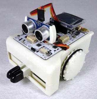
The attached video shows the wireless control of a Sparki Robot car using an infrared (IR) wireless remote controller.
Supplies
– An Arduino UNO, or compatible clone
– IR Receiver
– IR Transmitter (Any transmitter/brand will do)
– Dupont Hookup Wires
– Three different colored LEDs (I used larger ones in Red, Yellow, and Green. However, any three (3) different colors and any size such as 3mm, 5mm, 8mm, or 10mm, etc. will work)
– Three current limiting resistors for the LEDs (any resistor value from 220 ohm to 470 ohm will work as well, and any wattage for the resistors, that is 1/4 watt or above can be used)
– An optional experimental platform
In this introduction I used a Sparki and its remote controller to demonstrate wireless IR remote control. However, other than a close-up photograph, Sparki and its remote are not used in any of the Steps that follow.
Step 1: IR Receivers and Transmitters/Emitters
At the time of this publication, IR receiver LEDs could be purchased individually, from China in lots, for about $0.20 each,
IR receivers are available as separate un-mounted components (less expensive), or mounted on a module (more expensive).
However, you may find it easiest to use receivers mounted on a board (modules), although stand alone 1838s receivers, and their variants, can also be used.
I prefer the less expensive un-mounted receivers, although I do on occasion use a module.
The most common receiver, again when this was published, was the 1838, or one of its variants.
Typically an IR receiver has three pins: one for ground, one for Vcc (usually 5 volts DC), and the remaining one for the signal. Although there are typically only three wires, it is important to get the wires connected correctly or the receiver can be “fried”.
In the example kit, shown in the previous Step, the signal and ground wires on the IR receiver are clearly marked.
The Infrared (IR) receiver is clearly shown on the Sparki and is presented in an attached still picture. Sparki has a single infrared remote receiver which can interpret blinking infrared (IR) commands such as those presented in what follows.
As noted in the first Step, IR is invisible to the human eye, so pressing an IR transmitter will not normally show when a key has been activated.
Fortunately, most cameras, such as the ones in common use, or on smart phones, or tablets, do not have IR filters installed. Thus, the IR that was invisible unaided can normally be seen when an IR transmitter is held in front of a camera and a button pressed.
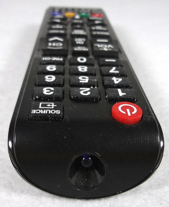
In the first (1st) still pictures I am using a remote from a deceased Samsung TV set. The TV, sadly, is no longer working, as unfortunately often occurs with Samsung TVs, but fortunately the remote is still operational, and can be used for other purposes.
You may also have a deceased TV or other appliance, but an operational IR remote that you can use with an Arduino, or other microcontroller.
Infrared remotes operate by transmitting IR signals through rapidly flashing IR light.
According to it’s documentation, “Sparki’s remote flashes 38,000 times a second.” It measures the time between blinking lights to determine which flashes represent a “One”. By counting these “Ones” it can determine a number, which is used to instruct Sparki what to do.
Sparki uses the NEC IR transmission protocol. See,
https://techdocs.altium.com/display/FPGA/NEC+Infra…
for more detail.
The essence of this decoding is shown in what follows in the next Steps, with examples.
IR remotes are commonly used in several different home appliances, not only TVs, but, stereos, sound bars, Blue-Ray, CD, ordinary DVD players, and Roku, as well as remote lighting control, etc.
The attached video shows an IR transmitter as seen through the display screen on a Canon (no IR filter) camera.
The Sketch in the next Step is used to “decode” a remote, i.e., to see what value is produced when a particular button is pressed.
In the first (1st) attached still photograph, in this Step, the IR transmitter’s light is visible through a cell phone camera.
Step 2: Decoding an IR Remote’s Keys
The following program is used to “decode” an IR remote and see what value it produces when a particular button is pressed.
Because this site has problems with less than and greater than brackets, and the text in between them, I have included a text file with the full Sketch.
I used the results found here to test IR input. The results are used in “if” statements, in the next Step, to determine what action(s) to take.
To use the program below, we use the built-in library “IRremote”.
We can locate this library using Sketch > Include Library > Manage Libraries. This will bring up the library manager in the Arduino IDE, and we want to insure that the program “IRremote” written by Shirriff is installed. If it is not, install the latest version of this library.
To use this library you create a receiver object, which you name. In our example, I named the receiver object IRReceiver in the line,
IRrecv IRReceiver(receiverPin);
I next enabled the receiving process using the command “irrecv.enableIRIn()”, where irrecv is the name of the receiver object we chose.
In our program we use
IRReceiver.enableIRIn();
to perform this enabling.
Note the “.” Identifies functions that are available for the object(s) we created. Thus, IRReceiver.enableIRIn() indicates that the function enableIRIn() is available to the IR object we created, IRReceiver.
In a similar manner we use the function decode(&results) with the object we created. The symbol “&” tells the function decode() that we are interested in the address of results. This available library function for our object returns “true” if a IR code is received and returns “false” if not yet received. When we receive an IR code, that result is stored in “results”. I
in our program we use,
if(IRReceiver.decode(&results)) { // Execute when an IR signal is
// received
In our sketch we print the value of “results.value”, which contains the IR code that was sent.
At the end of our sketch we use,
IRReceiver.resume();
This is necessary to allow the receiver to be ready to accept the next IR code sent.
To reiterate, and to summarize, before we even write the two mandatory functions void setup() and void loop() we need the following four lines,
(1) #include – // Include the built-in library IRremote by Ken Shiffiff
#include IRremote.h // Enclose IRremote.h in less than and greater than brackets as this sites removes these
// brackets and the text in between them.
(2) byte receiverPin = 6; // Establish the pin for the receiver output
(3) IRrecv IRReceiver(receiverPin); // Establish a receiver object
// here that object is named IRReceiver
(4) decode_results results; // Be alert for an IR code & when received store value in results
Note: If we “hard coded” the pin for the IR receiver, e.g., IRrecv IRReceiver(6), we would only have needed three lines before the two mandatory functions void setup () and void loop(). However, it is better coding practice not to “hard code” values where these might change in the future.
In the void setup() function we need to include,
IRReceiver.enableIRIn();
to enable our object to begin receiving. In the void loop () function, we use the variable results.value which contains the value of the IR code we receive.
/*
* Program written by: R Jordan Kreindler
* Date: Dec 11, 2020
* Sketch decodes values on IR remote
* Results are displayed on the Serial Monitor
*/
// Include the built-in library
// IRremote by Ken Shiffiff
#include IRremote.h // Include IRremote inside less than and greater than brackets as
// this site removes these brackets and the text inside them
//Establish IR receiver pin
byte receiverPin = 6;
// Create the IR receiver object
// Here I use the name IRReceiver
IRrecv IRReceiver(receiverPin);
// Store the results of our
// receive value in results
decode_results results;
unsigned long IRValueReceived;
void setup() {
// Start the Serial Monitor
// at 9600 baud
Serial.begin(9600);
// Enable the timer interrupt
IRReceiver.enableIRIn();
}
void loop() {
if (IRReceiver.decode(&results)) { // Execute when an IR signal is received
IRValueReceived = results.value;
Serial.print(“Remote type “);
if (results.decode_type == 3) {
Serial.print(“IR for Arduino, Yamaha, Roku, NEC, or Other: “);
}
else if (results.decode_type == 4) {
Serial.print(“Sony: “);
}
else if (results.decode_type == 7) {
Serial.print(“Samsung: “);
}
else {
Serial.print(“Unknown: “);
}
if (IRReceiver.decode(&results)) { // Execute when an IR signal is received
Serial.println();
// Print IR value in Decimal
Serial.print(IRValueReceived);
Serial.println(“\t\t\t Decimal”);
// Print IR value in Binary
Serial.print(IRValueReceived, BIN);
Serial.println(“\t Binary”);
// Print IR value in Hexadecimal
Serial.print(IRValueReceived, HEX);
Serial.println(“\t\t\t Hexadecimal”);
Serial.println(“Code Value of Key Pressed”);
Serial.println(“—–“);
IRReceiver.resume();
}
}
}
The output when the first (1st) three keys on my Samsung remote were pressed.
—-
Remote type Samsung:
3772784863 Decimal
11100000111000000010000011011111 Binary
E0E020DF Hexadecimal
Code Value of Key Pressed
—–
Remote type Samsung:
3772817503 Decimal
11100000111000001010000001011111 Binary
E0E0A05F Hexadecimal
Code Value of Key Pressed
—–
Remote type Samsung:
3772801183 Decimal
11100000111000000110000010011111 Binary
E0E0609F Hexadecimal
Code Value of Key Pressed
—–
Most papers use HEX IR codes, as they are more compact, but this is not necessary as binary or decimal codes will work as well. In fact, I use decimal codes in the next Step.
As noted, I checked the codes from the Samsung IR remote control, shown in an attached still photograph in this Step, and obtained the above results.
I have attached a video showing the output on the display monitor of what I obtained.
The Xinda IR remote is typical of the inexpensive remotes that can be found from Chinese sources, e.g., Aliexpress or on eBay, and they work well for controlling a variety of Arduino connected items such as LEDs, motors, relays, servos, steppers, etc.
They can work if you do not have a remote IR controller from a defunct appliance.
Source: Simple Inexpensive Wireless With Any IR Remote, Including No Longer Used Ones