Summary of Scintillino – an Arduino-based quick&dirty scintillation counter
This article details the construction of a low-budget scintillation counter using an Arduino Uno to detect ionizing radiation in real-time. The project utilizes a LYSO crystal and a KETEK Silicon photomultiplier (SiPM) housed in a light-tight cardboard enclosure with reflective tape. The system includes front-end electronics for biasing and signal processing, displaying data on an LCD or computer.
Parts used in the Scintillino:
- Scintillator crystal (1cmx1cmx2cm LYSO)
- Silicon photomultiplier (KETEKone)
- Resistors and capacitors
- Two fast rail2rail op-amps (OPA2354)
- DC-DC step-up converter
- Piezo buzzer
- Arduino Uno board
- LCD Keypad Shield
- Soldering iron and tin
- Cardboard
- Nylon ties
- Wires
- Thick plastic piece
- Upholstery foam
- White teflon tape
- Aluminium foil
Have you ever wondered about the radiation levels around you? Well today you can build your very own detector that measures ionizing radiation and displays data in real-time on an LCD (and also your computer if you want).
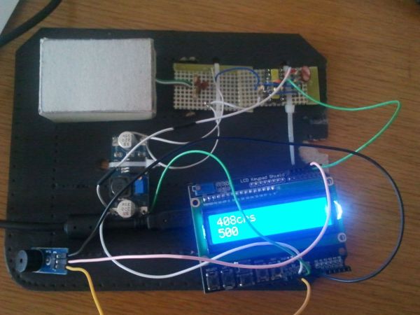
The visual design, as seen below, is perhaps a tad short of a Red Dot Award, but it sure works fine. It is a scintillation counter, no less and no more.
In fact, the game was all about doing it with the least amount of effort and nearly no budget, given that we already had a small scintillation crystal (LYSO) and a Silicon photomultiplier (SiPM) at hand. (Those were the only two expensive parts, at roughly $100 each. Sigh… We know…).
Our scintillator was supplied by Andy of http://pjtelect.com/. The SiPM is a KETEKone because they have a low breakdown voltage of 25V which makes it really cheap to bias them at around 30V….
What you will need:
– a scintillator crystal (we used a 1cmx1cmx2cm LYSO (Lu2Si2O7:Ce3+) but most any scintillation material should do)
– a Silicon photomultiplier (we prefer that over a PMT because HV biasing is easier and they are also harder to destroy)
– resistors, capacitors
– two fast rail2rail op-amps
– a simple DC-DC step-up converter off eBay
– a piezo buzzer for added dramatic effect
– Arduino Uno board
– LCD Keypad Shield (or another LCD, with minor adjustments to the Arduino sketch)
– soldering iron and tin (we use, lovingly, the old school non-ROHS stuff that will kill you etc etc yada yada)
– cardboard (for the motherboard), nylon ties
– a bunch of wires
– something to hold your SiPM tight against your crystal (we drilled holes into a scrap piece of thick plastic)
Now let’s get started!
Step 1: Setting up the scintillation detector
Scintillators work by eating up a gamma-ray and then emitting a burst of several thousand photons of visible light within the next few nanoseconds. This meagre amount of visible light is detected by a Silicon photomultiplier and converted into a pulse of electrical current.
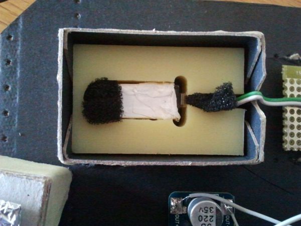
To measure light flashes this dim, we must obviously prevent any daylight from entering the detection chamber. For this reason we’ve constructed a cardboard box to enclose it.
Inside, we used a machined piece of thick plastic (because we had it, but duct tape or transparent epoxy would do, too) and some upholstery foam to press the scintillation crystal against the SiPM. You want good optical coupling here. The faces of the scintillator that are not facing the SiPM are wrapped in white teflon tape (yes, plumbing tape from HW store) to reflect as much light as possible toward the SiPM.
The top half of the box is a bit larger to fit over the bottom half. Make V cuts on both the bottom and the top half (as seen on the picture), so that you will be able to route the cables out of the box.
Tip: Depending on which you do first, the plastic or the box, make sure that the latter will fit the former.
Cover the scintillation thing with aluminium foil before closing the box. This will help keep out stray light….
… and your detector is ready!
Step 2: Some very high-fidelity nucleonics comin’ this way…
Front-end electronics.
The left side is the basic plain vanilla SiPM biasing circuit. Powered at 30V through the 10k resistor, with the ultra-fancy transimpedance stage being the 47ohm at left bottom. This is capacitively coupled to a two-stage discriminator that fires when the input pulse is large enough. Any fast rail-to-rail op-amp will do, and so does OPA2354 by Texas.
The hard part was soldering the darn smd package by hand to an old DIL socket. A shot of Gin steadied the hand and then all went well.
Ugly? Yes.
Works? Absolutely.
For more detail: Scintillino – an Arduino-based quick&dirty scintillation counter
- How does the scintillation detector work?
Scintillators absorb gamma-rays and emit visible light photons detected by a Silicon photomultiplier which converts them into electrical current pulses. - What material is used to reflect light toward the SiPM?
White teflon tape from a hardware store is wrapped around the scintillator faces not facing the SiPM to maximize light reflection. - Why was a Silicon photomultiplier chosen over a PMT?
A Silicon photomultiplier is preferred because high voltage biasing is easier and they are harder to destroy than traditional PMTs. - Can you use different scintillation materials?
Yes, most any scintillation material should work, though the author specifically used a 1cmx1cmx2cm LYSO crystal. - How do you prevent daylight from entering the detection chamber?
The detector is enclosed in a cardboard box covered with aluminium foil to keep out stray light and daylight. - What op-amp model is recommended for the circuit?
Any fast rail-to-rail op-amp will work, but the OPA2354 by Texas is specifically mentioned as a suitable choice. - How is the SiPM held against the crystal?
A machined piece of thick plastic with upholstery foam is used to press the crystal tightly against the SiPM for good optical coupling. - What voltage is used to power the SiPM biasing circuit?
The circuit is powered at 30V through a 10k resistor, taking advantage of the SiPM's low breakdown voltage of 25V.