Summary of Simple Garage Door Hack
Summary: A DIY solution uses a NodeMCU (ESP8266) and a 1-channel 5V relay to trigger a garage door motor by shorting its control contacts via a web interface. The project includes wiring, a 3D-printed enclosure, Arduino IDE setup with the esp8266 core and WebSockets library, fixed IP recommendation, and basic security notes. It is presented as a proof-of-concept rather than a production-ready system.
Parts used in the Simple Garage Door Hack:
- NodeMCU (ESP8266)
- 1 Channel 5V relay module
- USB outlet/charging device
- Mini USB cable
- Screws (M2*8)
- Connecting wire
- Heat-shrink tubing
- 3D printed enclosure (STL/FCSTD files)
After being accidentally locked out of my house on more than one occasion, I decided that there had to be better way to entering my home that did not involve breaking and entering (and without hiding a key outside somewhere).
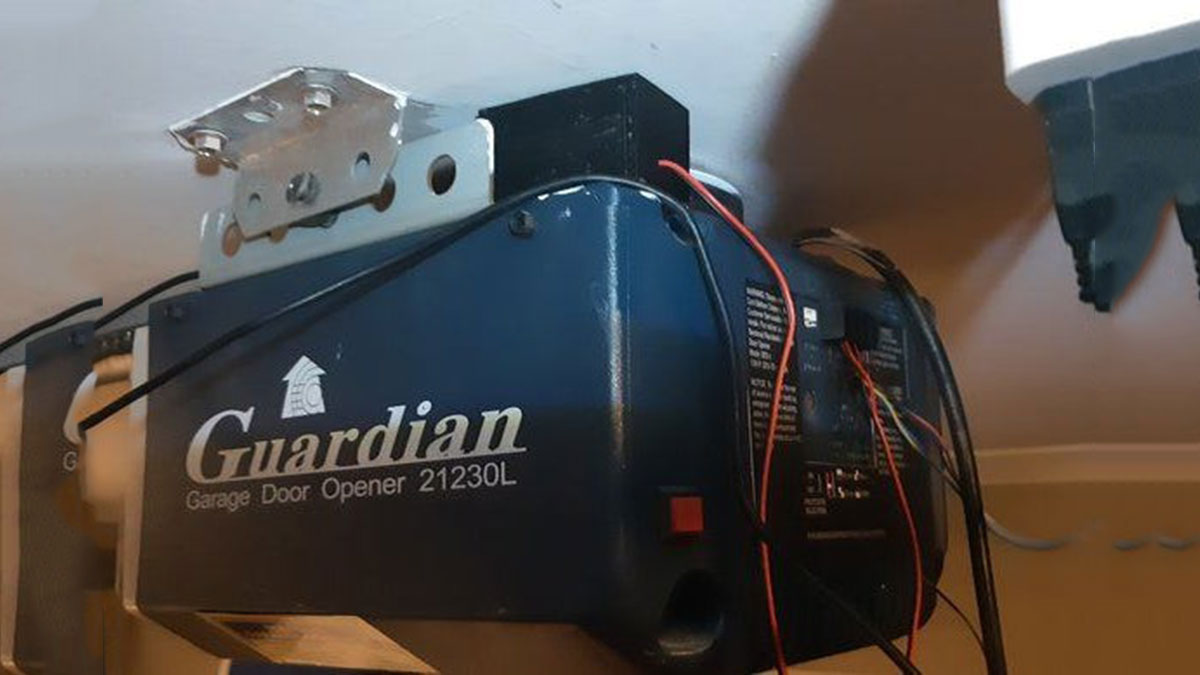
On taking a look at my garage door set-up I noticed that the motor to open the garage door could be activated by simply short-circuiting two contacts. On seeing this I realised that a very simply solution would be to connect an esp8266 to a relay that I could then trigger (to open or close the door) by connecting to the esp8266 controller using my mobile phone.
Step 1: Materials, Tools & Software
Materials
- NodeMCU
- 1 Channel 5V relay module
- USB outlet/charging device
- Screws(M2*8)
- min USB cable
Tools
- Soldering Iron
- Solder
- Heat-shrink tubing
- Wire-strippers
- Connecting wire
- 3D Printer
- Star screwdriver
- Pliers
Software
Step 2: Coding
The following library was added to the Arduino IDE: https://github.com/Links2004/arduinoWebSockets.git. Also if you have not already added the esp8266 library then this needs to be done as follows:
- Go to File > Preferences. In the “Additional Boards Manager URLs” field, type (or copy-paste) http://arduino.esp8266.com/stable/package_esp8266… and click ok.
- Then go to Tools > Board > Board Manager. Type “esp8266”
in the search field. The entry “esp8266 by ESP8266 Community” should appear. Click that entry and look for the install button on the lower right.
Not much more needs to be added here other than the code I used (GarageDoorHack-Final attached) was taken from https://gist.github.com/bbx10/667e3d4f5f2c0831d00b and modified slightly to accommodate what I needed to do i.e. to briefly trigger a relay when a button was click.
With reference to the code, make sure that you update the following lines to reflect your wireless SSID and PASSWORD:
- static const char ssid[] = “SSID”;
- static const char password[] = “PASSWORD”;
using the serial monitor (once you have uploaded the code) you will be able to see what IP is allocated to the NodeMCU.
One last point that is worth noting is that my NodeMCU board appeared to have the pins assigned differently to what is mentioned online i.e. my GPIO05 was pin 5 where as the the online reference that I was using said that it was 1 (or maybe my GPIO pins where assembled in a different order). Whatever the case, I had to use some trial and error before a could determine which pin was actually GPIO5.
Step 3: Putting It All Together
Steps followed:
- I clipped off all the NodeMCU pins that I was not using (yes I could have unsoldered them but I found this easier).
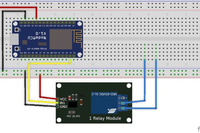
- Soldered connecting wires onto the relevant pins (as be diagrams and photos above), using heat-shrink tubing to insulate the connections.
- 3D Printed the case (STL files attached; the FCSTD file is the FreeCAD file).
- Screwed the NodeMCU board down. The screws that I had were too long and so a used pliers to snip them shorter.
- Pushed the top of the relay into the square holder in the lid which held it firmly in place. The orientation was such that the relay contacts faced the wire exit hole in the lid.
- Attached the lid and screwed it closed.
- Connected the relay wires to the garage door motor terminals.
- Plugged the project into the USB power source.
- Waited for the NodeMCU to authenticate with the wireless.
- Browsed to the IP address from my phone.
- Tested by pressing the button.
The threaded screws that I had worked well but self-tapping ones would have been easier to work with.
Step 4: Final Comments
The following falls outside the scope of this Instructable but are worth discussing:
IP Address
By default your router will issue random IP Addresses meaning that your device might not always have the same IP which would then make it very difficult to find and access from your phone. It is therefore important that you assign it a fixed IP. There are two main ways to do this, each with their own pros and cons. My preference is to allow the router’s DHCP server to do this. The general steps to follow when using this method are:
- Log onto your router as an admin.
- Look at the DHCP logs and record the MAC address associated with the IP address that was issued to your NodeMCU.
- Find the menu option that allows you to set IP reservations. Here you will be able to specify a MAC address and the IP that you wish this MAC address to always to get.
I usually do the above as early as possible in my projects.
Creating a shortcut on your phone
- Make sure that you are connected to the same wireless network as your device.
- With the IP address now fixed you should be able to browse to it on your phone.
- Save the IP as a bookmark.
- Save the bookmark to your phone’s home page.
Security
Anyone connected to your wireless network will be able to browse to this IP and trigger the relay. To do this they will then have to know your Wireless SSID and password. For the average user this is probably enough security. If you wanted a higher level of security you could implement some sort of MAC filtering on your router or a standalone server or you could try a two-factor authentication approach. This said, if someone knows how to hack your network then they probably know how to hack all of the above solutions too. Further if they are really that keen to get in they will probably simply break in.
In short if you live in a low risk environment then you probably have nothing to fear. On the other hand if you live in a high risk environment then you probably have more important things to worry about and a garage door hack.
Having said all of this, the following project is more of a proof-of-concept project and not meant as a full-scale production implementation. Anyone implementing this project does so at their own risk.
Closing comments
Sometimes the connection to the NodeMCU appears to get lost. When this happens you just need to refresh the webpage and it should reconnect successfully.
And lastly, instead of connecting the controller directly onto the door motor, I could have wired it in parallel with the manual switch in the garage. While this would have enabled me to hide the circuitry in the wall, I would have then had to make another plan with respect to powering the device. The power issue would have been relatively easy to solve but for the time being I did not feel that the effort would be worthwhile.
All in all this is a simple and cheap project that I enjoyed completing.
Latest Developments
Visit https://www.instructables.com/id/Simple-Garage-Doo… to see version two of the Simple Garage Door Hack.
Source: Simple Garage Door Hack
- What components do I need to build the Simple Garage Door Hack?
The article lists a NodeMCU, 1 channel 5V relay module, USB power outlet, mini USB cable, M2*8 screws, connecting wire, heat-shrink tubing, and a 3D printed enclosure. - How do I program the NodeMCU for this project?
Use the Arduino IDE with the esp8266 board package installed and add the arduinoWebSockets library, then upload the provided GarageDoorHack-Final code after setting your SSID and PASSWORD. - How is the relay connected to the garage door?
The relay contacts are wired to the garage door motor terminals to short the control contacts when triggered. - How do I find the NodeMCU IP address after uploading the code?
Use the Arduino IDE serial monitor after uploading to see the IP address allocated to the NodeMCU. - How can I ensure the NodeMCU keeps the same IP address?
The article recommends reserving an IP for the NodeMCU in your router's DHCP settings using the device MAC address. - Can I access the garage door control from my phone?
Yes; browse to the NodeMCU IP address from your phone on the same Wi-Fi network and press the web button to trigger the relay. - What security considerations are mentioned?
Anyone on the same wireless network can trigger the relay; the article suggests using router MAC filtering, a standalone server, or two-factor approaches for higher security but notes this is a proof-of-concept. - What should I do if the connection to the NodeMCU is lost?
Refresh the webpage; the article states that reconnecting typically works by refreshing. - Could the relay be wired differently to be less visible?
The author notes wiring in parallel with the manual garage switch is possible but would require addressing power placement and was not implemented. - Where can I find version two of this project?
The article points to the Instructables page for Simple Garage Door Hack version two.