
Summary of Simple digital code lock using arduino
This article details a simple digital code lock project using an Arduino. The system utilizes a hex keypad where specific keys (A for lock, B for unlock) and digits 1–6 form the combination. A solenoid lock, represented by an LED in the circuit diagram, is controlled via a digital pin to secure or release based on the entered code.
Parts used in the Digital Code Lock:
- Arduino board
- Hex keypad
- Solenoid lock
- LED D1
- Resistor R1 (330 ohm)
Digital code lock or digital combination lock are a type of digital locks where a combination of digits/characters or both are used for unlocking the lock. This article is about a simple digital code lock using arduino. Here the code consists of a combination of digits from 1 to 6.
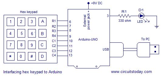
There are separate keys for locking and unlocking the system. The system can be unlocked by pressing the unlock button after entering the correct combination of digits. A hex key pad is used as the input device. Only the first two rows of key (1, 2, 3, A, 4, 5, 6, B) are used in this project. A is used for locking the system and B is used for unlocking the system. Read this article Interfacing hex keypad to arduino for knowing more about hex keypad and its interfacing to the arduino. The circuit diagram of the digital code lock using arduino is shown in the figure below.
Circuit diagram.
Row pins R1 to r4 are interfaced to digital pins 6 to 9 of the arduino. Column pins C1 to C4 are interfaced to digital pins 10 to 13 of the arduino. Digital pin 3 of the arduino is configured as the output pin for delivering the control signal for the solenoid lock. The program and circuit is designed on the assumption that the solenoid lock will “lock” for a low signal at its input and “unlock” for a high signal at its input. In this circuit the solenoid is represented by the LED D1. LED ON means “unlocked” and LED OFF means “locked”. 330 ohm resistor R1 limits the current through the LED.
For more detail: Simple digital code lock using arduino
- What type of lock is described in the article?
The article describes a simple digital code lock using an Arduino. - How many digits are used in the combination?
The code consists of a combination of digits from 1 to 6. - Which keys are used for locking and unlocking?
Key A is used for locking the system and key B is used for unlocking it. - Which rows of the hex keypad are utilized in this project?
Only the first two rows of the keypad are used. - How are the row pins connected to the Arduino?
Row pins R1 to r4 are interfaced to digital pins 6 to 9 of the Arduino. - How are the column pins connected to the Arduino?
Column pins C1 to C4 are interfaced to digital pins 10 to 13 of the Arduino. - Which Arduino pin controls the solenoid lock signal?
Digital pin 3 is configured as the output pin for the control signal. - What signal level locks the solenoid?
A low signal at the input causes the solenoid lock to lock. - How does the LED indicate the lock status?
LED ON means unlocked and LED OFF means locked. - What is the function of resistor R1?
The 330 ohm resistor limits the current through the LED.
