Summary of Simple Basement Security System using Arduino
This project builds a simple room security system based on an ATtiny85 that monitors a reed switch and a key switch and triggers a 12V buzzer via a BC547 transistor. Power is provided by a 12V source and regulated to 5V with an LM7805 for the ATtiny85. The guide includes parts sourcing, PCB layout hints, and wiring instructions; watch the video and follow the provided schematic and PCB layout for best results.
Parts used in the Simple Basement Security System:
- Arduino Uno (as programmer for ATtiny85)
- ATtiny85
- Reed switch
- Key switch
- IC socket
- 12V buzzer
- BC547 NPN transistor
- 10kΩ resistors (4x)
- 1kΩ resistor (1x)
- 640Ω resistor (1x)
- 10µF capacitors (2x)
- 0.1µF (100nF) capacitors (2x)
- Push button
- LM7805 5V linear regulator
- DC jack
- Stripboard / PCB (striped)
- Male headers
- Female headers
- Red LED 5mm
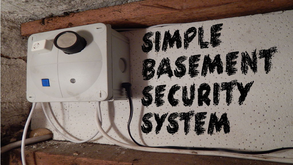
In this project I will show you how to build a very simple security system for all kinds of rooms. It might be simple but still effective. It is based around an Attiny85 and uses a reed switch and a key switch as inputs to see whether an intruder has accessed the room. A buzzer will then notify you or other persons. Let’s build it
The video gives you all information to build this simple security system. But I will cover the most important steps again.
Step 2: Order your parts!
As always, you can’t build stuff without the correct parts. Here is my material list with example sellers for your convenience:
Ebay:
1x Arduino Uno (as programmer for Attiny85):http://rover.ebay.com/rover/1/711-53200-19255-0/1?…
1x Attiny85:http://rover.ebay.com/rover/1/711-53200-19255-0/1?…
1x Reed Switch:http://rover.ebay.com/rover/1/711-53200-19255-0/1?…
1x Key Switch:http://rover.ebay.com/rover/1/711-53200-19255-0/1?…
1x IC Socket: http://rover.ebay.com/rover/1/711-53200-19255-0/1?…
1x 12V Buzzer:http://rover.ebay.com/rover/1/711-53200-19255-0/1?…
1x BC547 NPN Transistor: http://rover.ebay.com/rover/1/711-53200-19255-0/1?…
4x 10kΩ, 1x 1kΩ, 1x 640Ω Resistor (1/4W):http://rover.ebay.com/rover/1/711-53200-19255-0/1?…
2x 10µF Capacitor: http://rover.ebay.com/rover/1/711-53200-19255-0/1?…
2x 0,1µF(100nF) Capacitor:http://rover.ebay.com/rover/1/711-53200-19255-0/1?…
1x Push Button:http://rover.ebay.com/rover/1/711-53200-19255-0/1?…
1x LM7805 (5V linear regulator):http://rover.ebay.com/rover/1/711-53200-19255-0/1?…
1x DC Jack:http://rover.ebay.com/rover/1/711-53200-19255-0/1?…
1x PCB (striped) :http://rover.ebay.com/rover/1/711-53200-19255-0/1?…
1x Male Headers:http://rover.ebay.com/rover/1/711-53200-19255-0/1?…
1x Female Headers:http://rover.ebay.com/rover/1/711-53200-19255-0/1?…
1x Red LED 5mm: http://rover.ebay.com/rover/1/711-53200-19255-0/1?…
Amazon.de:
1x Arduino Uno (as programmer for Attiny85): http://amzn.to/1tZNXjZ
1x Attiny85: http://amzn.to/1qKReWK
1x Reed Switch: http://amzn.to/1oO2b5Q
1x Key Switch: http://amzn.to/1oO2jCh
1x IC Socket: http://amzn.to/1tZPcQ0
1x 12V Buzzer: http://amzn.to/1qKSkSx
1x BC547 NPN Transistor: http://amzn.to/1tZPWVq
4x 10kΩ, 1x 1kΩ, 1x 640Ω Resistor (1/4W): http://amzn.to/1A2KZzi
2x 10µF Capacitor: http://amzn.to/1tZRcrz
2x 0,1µF(100nF) Capacitor: http://amzn.to/PD2jZj
1x Push Button: http://amzn.to/1qKUxgG
1x LM7805 (5V linear regulator): http://amzn.to/1qKUGAC
1x DC Jack: http://amzn.to/1oO2b5Q
1x PCB (striped) : http://amzn.to/1qKV2Hy
1x Male Headers: http://amzn.to/1qKVg1p
1x Female Headers: http://amzn.to/1tZTmHV
1x Red LED 5mm: http://amzn.to/1qKVuWm
Amazon.com:
1x Arduino Uno (as programmer for Attiny85): http://amzn.to/1BGO7iD
1x Attiny85: http://amzn.to/ZixmOf
1x Reed Switch: http://amzn.to/1BGOBVM
1x Key Switch: http://amzn.to/1EgGOCf
1x IC Socket: http://amzn.to/1EgGTG0
1x 12V Buzzer: http://amzn.to/1oIFpu8
1x BC547 NPN Transistor: http://amzn.to/1EgHLdT
4x 10kΩ, 1x 1kΩ, 1x 640Ω Resistor (1/4W):http://amzn.to/1upkTo4
2x 10µF Capacitor: http://amzn.to/ZizN3p
2x 0,1µF(100nF) Capacitor:http://amzn.to/1yFH4KK
1x Push Button: http://amzn.to/1EgI7kI
1x LM7805 (5V linear regulator):http://amzn.to/1n69hVK
1x DC Jack: http://amzn.to/1rYWQNd
1x PCB (striped) : http://amzn.to/1vElUHb
1x Male Headers: http://amzn.to/ZiC1Qm
1x Female Headers: http://amzn.to/Z4IZId
1x Red LED 5mm: http://amzn.to/1yFI9lN
Step 3: Build the circuit and connect the external parts!
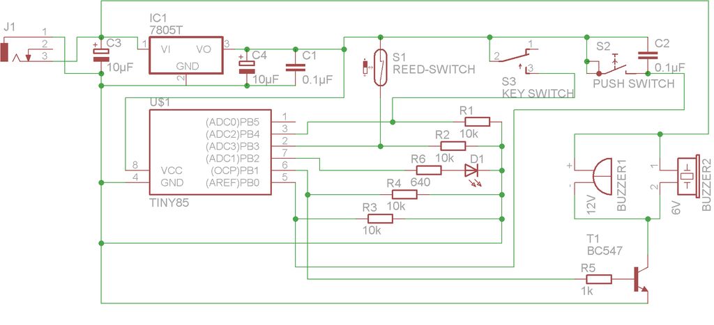
Here you can find the schematic for the circuit. I also uploaded my layout for the stripped PCB. If you build it exactly according to my layout then the chances are higher that everything will work in the end.
And don’t forget to make interruptions in the copper traces! Those are the yellow dots in the second layout.
If you managed to finish the circuit then go ahead and connect the external parts like the reed switch or the key switch to the main PCB. Use my picture of the PCB as a reference.
For more detail: Simple Basement Security System using Arduino
- What is the main microcontroller used in the project?
The project uses an ATtiny85 as the main microcontroller. - Do I need an Arduino Uno for this project?
Yes, an Arduino Uno is used as a programmer for the ATtiny85. - What sensors or switches detect intrusion?
The system uses a reed switch and a key switch as inputs to detect access. - How is the buzzer driven?
A 12V buzzer is driven via a BC547 NPN transistor controlled by the ATtiny85. - What supplies power to the ATtiny85?
A 12V source is used with an LM7805 linear regulator to provide 5V to the ATtiny85. - Are there schematic and PCB layout resources provided?
Yes, the guide includes the schematic and a PCB layout for the stripboard, including where to break copper traces. - What passive components are required?
The build uses resistors (10k, 1k, 640Ω), capacitors (10µF and 0.1µF), and an LED. - Is a specific PCB layout recommended?
Yes, following the provided PCB layout increases the chance the circuit will work correctly.