Summary of Arduino Powered Autonomous Vehicle
Summary: This project builds an Arduino-powered autonomous RC car that navigates GPS waypoints while avoiding obstacles using a magnetometer, ultrasonic sensor, and motor shield. The author retrofits an inexpensive RC chassis, mounts electronics on a board, and controls behavior with an Arduino sketch that handles GPS, compass heading, obstacle detection, motor control, and an LCD status display.
Parts used in the Autonomous RC Car Project:
- Radio controlled (RC) vehicle chassis
- Arduino Uno microcontroller
- Adafruit Motor Shield v2
- Adafruit Ultimate GPS Shield (or breakout)
- Adafruit HMC5883 Magnetometer
- HC-SR04 ultrasonic distance sensor
- LCD display (2-line or 4-line)
- Infrared sensor and remote (optional)
- Thin wood board (mounting platform)
- Breadboards (main and small)
- Jumper wires
- Surgu (for mounting ultrasonic sensor)
- Soldering iron and solder
- Drill
A few months back I started playing around with Arduino micro controllers as a learning exercise (and for fun); this project is the culmination of that. The goal of the project was to create a vehicle that can autonomously navigate through a series of waypoints (GPS coordinates) while avoiding any obstacles it encounters along the way.
The project uses an assortment of electronic sensors and components, and pulled together the knowledge I had learned and synthesized from many sources along the way.
In the attached video you can see a short clip of the car on its way, in this run it navigated through five GPS waypoints on a course on my neighborhood streets totaling about 300 meters.
Step 1: Component List & Project Cost
The main components were the following:
- A basic radio controlled (RC) vehicle. Can be a basic one like I used which are available in the $15 range. If you want to spend a bit more, get one with proportional steering and four wheel drive. The one I used was similar to this one from Amazon.com (though it came from Wal-Mart and at a lower price at the time).
- An Arduino Uno micro controller. Amazon.com $24
- A motor shield to control the two electric motors and allow for a separate motor power supply. Adafruit Motor Shield v2 $19.95.
- A GPS for navigation. Adafruit Ultimate GPS Shield $49.95 (or breakout for $39.95)
- A magnetometer for compass navigation. Adafruit HMC5883 Magnetometer $9.95
- An HC-SR04 ultrasonic distance sensor for object avoidance. Amazon.com $6.00
- An LCD display to display vehicle status and information. Yourduino.com $5.75 (I later upgraded to a 4-line LCD for about $12)
- An infrared sensor & remote. Optional, added some convenience but not required for the project. I already had these components from a previous kit from Yourduino.com
- And of course an Arduino sketch (a C++ program) to control everything (code attached in this Instructable)
Additionally, the project used the following smaller components and accessories:
- A thin wood board as a mounting platform; acrylic or other would have worked (and probably looked better!), but this is what I was able to find at local hobby shops
- Breadboard(s) for making connections. I used a long narrow breadboard for the main connections, and a very small breadboard (that originally came with a proto-shield) so that I could mount the magnetometer as far from the other electronics as possible
- Jumper wires
- Surgu for mounting the ultrasonic sensor. Amazon.com $12
The following tools were used:
- Soldering iron & solder
- Drill
The rough project cost is around $120 – 150 depending on what components you may already have.
A note on project cost: other than the mounting board, almost all of the other components are re-usable; either things you already have that you can use for this project, or things that we can eventually disassemble from this project and re-use elsewhere.
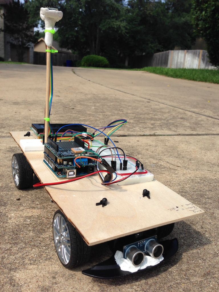
Step 2: Vehicle Chassis and Mounting Platform
I had seen posts on the internet about hacking inexpensive radio controlled (RC) cars and directly connecting an Arduino to the existing circuit board. I happened to have such a car around that my 3 year old no longer played with; it was a $15 Wal-Mart RC car.
Unfortunately, my early soldering skills left a lot to be desired and I burned through a couple the delicate surface mount components, so I ended up with a partially functioning vehicle.
Plan B: I ripped out the car’s entire control board and purchased an Adafruit Motor Shield (v2). Problem solved. Now I had full control over the vehicle’s motors…though they were pretty basic.
The car was controlled by two DC motors: one controlled the drive, and using the pulse wave modulation (PWM) of the motor controller I was able to control the speed across a range of speeds; the other controlled the steering. This inexpensive RC car did not have proportional steering; the left and right wheels are joined, and there is a spring in the middle that holds the wheels in neutral (center) position when the DC motor is not engaged. When the motor is engaged, it goes to a full/hard turn left or right. That allowed me to turn the vehicle, but provides limitations later when I want more sophisticated navigation. For a future enhancement I will try to replace the DC motor with a servo for full proportional steering control.
I used a thin board as a mounting surface on which I attached the breadboards, Arduino, LCD, etc. I placed the battery supplies beneath the board and passed the cables through holes I drilled.
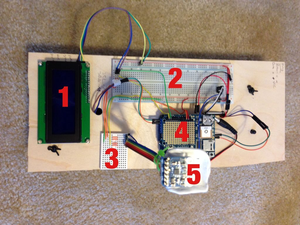
In the first photo above, you see (1) the LCD, (2) the main breadboard, (3) the small breadboard for the magnetometer, (4) the Arduino (you are seeing the GPS Shield as you look down), and (5) the magnetometer sitting up high on its pole mounted perch.
Step 3: Program Logic
The Arduino is controlled through a C++ program (“sketch”). The main action happens in the Arduino sketch loop() function which runs repeatedly. The basic program control logic is:
- Check to see if the kill switch was pressed (if enable in the configuration).
- Process any new GPS information and update the course and distance to the target. Move on to the next waypoint if we have reached the current destination.
- Read compass to get current bearing and decide the desired direction to turn the car
- Move the vehicle and check for any obstacles we need to avoid.
- Update LCD display
The code to handle each of these is in separate functions.
Fully documented source code is attached.
 waypointClass.h436 bytes
Step 4: LCD Display
The LCD provides invaluable insight what the vehicle is doing, critical for debugging and tuning the code. It also looks cool!
While running, the main screen shows the following information:
Row 1:
1. tH = Target Heading, the course to the current waypoint;
2. cH = Current Heading, the direction the vehicle is actually facing
Row 2:
3. Err = Error (in degrees) between the target heading and compass heading; this is a signed value indicating which direction (left or right) the vehicle needs to turn to intercept the target heading;
4. Dist = Distance (meters) to the current waypoint; you will notice the small inline bar graph showing the remaining distance to this waypoint.
Row 3:
5. Snr = Sonar distance, i.e. the distance to any objects in front of the vehicle. Also has an line bar graph from 0 to the maximum detectable distance;
6. Spd = Speed of vehicle (0-255)
Row 4:
7. Mem = Memory (in bytes) of free memory; the Arduino Uno only has 2k so I had to watch this closely;
8. WPT n OF x; shows where the vehicle is in the list of waypoints.
Step 5: Object Avoidance
To drive autonomously, the vehicle needs to be able to check for and avoid obstacles it encounters as it drives. I handle this with a “ping” ultrasonic sensor and some computer logic.
The sensor is a basic ultrasonic sensor. I combined that with the Arduino NewPing library, which is a big improvement over the original Ping library (among other things, it only requires a single shared pin for both send & receive).
The sensor is pretty basic, and has a very narrow field of view. For this project, I am only using a single sensor with a fixed position (not a sweeping “radar” type implementation).
I mounted the sensor to the front bumper of the vehicle with some Surgu. This was my first time using the product, and it works very well. I only used a single 3.5g packet, and that was sufficient for this purpose.
The sensor has a tendency to return the occasional odd or random value…not sure why. In his excellent series of articles, Miguel Grinberg offers a simple solution: use a moving average. I adopted his MovingAverage class to the project with good results.
The checkSonar() routine continually takes new measurements, adding each new measurement to the moving average; the average is then used for program logic.
If an object is detected, the following logic is applied:
- Slow down
- If the vehicle is going straight (not turning), turn in the direction closest to our waypoint (technically, closest to the course to our waypoint).
- If the vehicle is already turning, then turn in the opposite direction to try to avoid the object.
- If we get within a definable distance (TOO_CLOSE) of the object, stop, backup, and try again.
Once we have a clear path ahead, normal navigation resumes.
For more detail: Arduino Powered Autonomous Vehicle
- What is the goal of the project?
To create a vehicle that autonomously navigates GPS waypoints while avoiding obstacles. - What microcontroller is used?
An Arduino Uno is used. - How does the vehicle determine its position and heading?
It uses an Adafruit Ultimate GPS Shield for position and an Adafruit HMC5883 magnetometer for heading. - What component handles motor control?
An Adafruit Motor Shield v2 controls the two DC motors and allows a separate motor power supply. - How does the car detect obstacles?
It uses an HC-SR04 ultrasonic distance sensor with the NewPing library and a moving average for measurements. - What happens when an object is detected?
The vehicle slows, chooses a turn direction based on waypoint/course and current turn, and if too close it stops, backs up, and retries. - What information is shown on the LCD?
The LCD shows target heading, current heading, heading error, distance to waypoint with a bar graph, sonar distance with a bar graph, speed, free memory, and waypoint index. - Can the RC car chassis provide proportional steering?
The inexpensive chassis used did not have proportional steering; it had full left/right via a DC motor, and the author plans to try a servo for proportional steering later. - What software structure controls the vehicle?
An Arduino sketch implements a loop that checks a kill switch, processes GPS updates, reads the compass, moves the vehicle with obstacle checks, and updates the LCD.