Summary of SIMON SAYS BOX
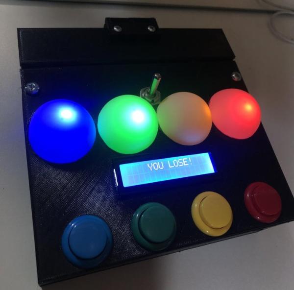
This project is a "Simon Says Box" combining the memory game Simon with a Useless Box mechanism. It features four colored LEDs and buttons, an LCD screen for score tracking, and two servo motors that reveal a "Sucker!" sign upon losing. The game progresses through 100 levels of increasing difficulty, with automatic resets on failure or timeout.
Parts used in the Simon Says Box:
- Arduino board
- Six volt power source (battery pack with four AA batteries)
- Four arcade buttons
- Four LEDs
- I2C LCD screen
- Two servo motors
- On/off toggle switch
- Ping pong balls (cut in half)
- 3D printed box, lid, hinge, motor casings, arms, and sign
Authors:
Jackelyn Garcia- [email protected]
Hector Villalobos- [email protected]
Allan Hambly- [email protected]
(For more questions contact us at our emails above)
Here is the YouTube video for our project:
Acknowledgements:
California Maritime Academy (ET Department)
Professor Chang-Siu
Erin Cole
Gage Sturgeon
Jack Whelan
The Idea:
The Simon Says Box is a combination between the game Simon and an Arduino project called The Useless Box, along with our own touches. In our game, there are four different colored LEDs that will randomly display a sequence of colors. At the start of the game, one color is displayed in which the player is to correctly match it by pressing the corresponding colored button. If the color is correctly matched, the game will add a second color in addition to the first. Each time the colors displayed are matched in the correct order, the players moves on to the next level where one more color is added to the previous pattern. This tests the player’s ability to memorize the patterned sequences and makes it more challenging as they move on to each level. An LCD screen was incorporated in order to keep track of what level the player is on and also designate when the player has lost (this is part of our losing sequence). In addition, our losing sequence includes the function of two servo motors, with arms attached to them, that work together to bring out a customized 3D printed sign that may say something like “Sucker!” The game is programmed to go up to 100 levels, making the game almost impossible to beat, so good luck in trying to beat it!
Supplies
Here is a spreadsheet containing all the items used, their according prices, where to purchase:
Step 1: Project Functionality
Description:
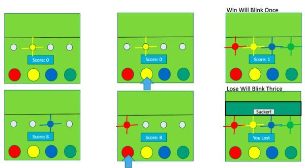
Once the game is turned on by flipping the switch, a greeting state will initiate to then begin the game play state. As demonstrated above, the game play state commences by having a random light (in this case yellow) blink. The player has 3 seconds to press the correct button (the arrow signifies the pressing of the button) in order to pass this level. When the correct button pressed is detected, all the lights will blink once in order to signify the completion of that level and to prepare the player for the next sequence. There are two ways in which a player can lose. The first, as mentioned, if the player exceeds more than 3 seconds without pressing the correct button (per light) the losing sequence will initiate which is shown in the bottom right figure. The second way to lose is demonstrated by the lower half of the figures. In this case, the light to match is the color blue, however the player has incorrectly pressed the red button which then triggers the lose sequence. The game will automatically restart after this.
Step 2: Circuit Diagram
Description:
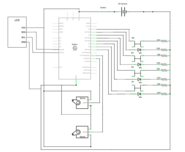
Our circuit is powered by a six volt source which comes from a battery pack containing four AA batteries. This is more than enough power to power all our elements. Our six volt source powers the Arduino, servo motors, and LCD screen directly. The Arduino regulates the six volts to provide five volts for all four of our arcade buttons and four LEDs. The LEDs, arcade buttons, and servo motors are all connected to the digital pins of the Arduino, however the LCD screen we used, connects to the A4 and A5 analog pins. We were fortunate to have an I2C LCD screen which comes with a built in potentiometer and reduces the amount of pins needed for it to work. Typical LCD’s will require a lot more digital pins which minimizes the pin availability for other components. Lastly, our on/off toggle switch was wired to the positive side of the battery pack and then grounded. The battery pack comes with an on and off switch that we left on so that the toggle switch is means of turning the game on or off.
Power Consumption:
Our power source which comes from the four AA batteries provides us with six watts of power to work with. Each servo motor uses five volts and takes 360 mA of current which results in a power draw of 1.8 watts each (x2 servo motors). The Arduino also runs off of five volts and takes 80 mA of current which results in a power draw of 0.4 W. The LEDs operate at three volts and 30 mA, drawing 0.09 watts each (x4 LEDs). Finally, the LCD screen operates at five volts and 30 mA of current which draws 0.15 watts of power. This results in a total power draw of 4.51 watts which means 75.17% of our power is used with a remaining 24.83% readily available.
Step 3: State Machine Diagram
Description:
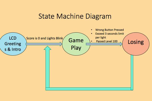
Above, the state machine diagram of our game is shown. As shown, once the game is switched on, it will start by first displaying a greeting and introduction on the LCD screen. Once the greeting and introduction state is over it will prepare for the game play state by displaying a score/level of zero on the LCD screen and blinking the light in order to signify that the game is about to start. During the game play state, one LED will blink at random so that the player starts off by matching one light during the first level. The game will then check is the player has pressed the right button and if that is true it will throw out a total of “n” number of lights to match. This means every time the correct pattern is matched, one more random light is displayed in the next level in addition to the current pattern. The game play state will continue on until a wrong button is pressed, the player exceeds the 3 second limit time frame to press the correct button, or level 100 is passed. Then the losing sequence will then occur in which the LCD screen displays a message such as “YOU LOSE!” and the servo arms will work together to bring out the 3D printed sign that says “SUCKER!” The game then automatically resets.
*Note: Our game does not have a winning sequence because passing level 100 is highly improbable. This is why even if you were to pass level 100 some how it is still designed to transition in to the losing sequence.
Step 4: Code
Introduction and Greeting
#include <LiquidCrystal_I2C.h>
#include<Wire.h>

char array1[] = "Simon Says!  ";
char array2[] = "Hello, Player";
char array3[] = "Lets Play   ";
char array4[] = "YOU LOSE!";


LiquidCrystal_I2C lcd(0x27, 16, 2);<br>
lcd.init();
  lcd.backlight();

  lcd.setCursor(15, 0); // set the cursor to column 15, line 0
  for (int positionCounter = 0; positionCounter < 13; positionCounter++)
  {
    lcd.scrollDisplayLeft(); //Scrolls the contents of the display one space to the left.
    lcd.print(array1[positionCounter]); // Print a message to the LCD.
    delay(tim); //wait for 250 microseconds
  }

delay(1500);

  lcd.clear(); //Clears the LCD screen and positions the cursor in the upper-left  corner.
  lcd.setCursor(15, 0); // set the cursor to column 15, line 1

  for (int positionCounter = 0; positionCounter < 13; positionCounter++)
  {
    lcd.scrollDisplayLeft(); //Scrolls the contents of the display one space to the left.
    lcd.print(array2[positionCounter]); // Print a message to the LCD.
    delay(tim); //wait for 250 microseconds
  }

  delay(1500);<br>
The first state consists of the LCD screen displaying the proper introduction and greeting. The first chunk of code is provided for you to see what LCD library we used as well os what each of our arrays stand for. The second chunk of the code is simply for the LCD introduction messages in which we included in our setup so that it will always begin by displaying this message when the game is turned on. The lcd.init() and lcd.backlight() are required to always be stated in order for the LCD properties to function. The lcd.cursor() function allows you to describe what location you want to start your cursor at which will display the first letter of your message. The ‘for’ statement allowed us to display our messages with a scrolling effect which shifted to the words towards the let side of the LCD screen.
Game Play State
<strong><br></strong> //The actual game will begin. Random LEDS will begin to genetate and be outputted to the user.
    for (int y = 0; y <= 99; y++)
    {
      //function for generating the array to be matched by the player
      digitalWrite(ledpin[0], HIGH);
      digitalWrite(ledpin[1], HIGH);
      digitalWrite(ledpin[2], HIGH);
      digitalWrite(ledpin[3], HIGH);


        delay(25);
      }

      digitalWrite(ledpin[0], LOW);
      digitalWrite(ledpin[1], LOW);
      digitalWrite(ledpin[2], LOW);
      digitalWrite(ledpin[3], LOW);
      delay(1000);

      for (int y = turn; y <= turn; y++)
      { //Limited by the turn variable
        Serial.println(""); //Some serial output to follow along
        lcd.print("Score: ");
        lcd.print(score);
        score++;
        Serial.print(y);
        Serial.println("");
        randomArray[y] = random(1, 5); //Assigning a random number (1-4) to the randomArray[y], y being the turn count
        for (int x = 0; x <= turn; x++)
        {
          Serial.print(randomArray[x]);

          //This for loop will output the randomly generated LEDs to the user
          for (int y = 0; y < 4; y++)
          {

            if (randomArray[x] == 1 && ledpin[y] == 8)
            { //if statements to display the stored values in the array
              digitalWrite(ledpin[y], HIGH);

              delay(400);
              digitalWrite(ledpin[y], LOW);
              delay(100);
            }

            if (randomArray[x] == 2 && ledpin[y] == 9)
            {
              digitalWrite(ledpin[y], HIGH);

              delay(400);
              digitalWrite(ledpin[y], LOW);
              delay(100);
            }

            if (randomArray[x] == 3 && ledpin[y] == 10)
            {
              digitalWrite(ledpin[y], HIGH);

              delay(400);
              digitalWrite(ledpin[y], LOW);
              delay(100);
            }

            if (randomArray[x] == 4 && ledpin[y] == 11)
            {
              digitalWrite(ledpin[y], HIGH);

              delay(400);
              digitalWrite(ledpin[y], LOW);
              delay(100);
            }
          }
        }
      }
      //Will go into the input function and check and see if user input mathced program generated LED
      input();
This part of the code allows us to begin the game play state. As mentioned the game play state starts off by blinking all the lights once so LED’s are put HIGH then LOW in order to give off the blinking effect. The score/level is also started off at zero and is dependent on the turn counter which we named ”turn”. The LCD will print the according score/level and will add one point for the next time it has to display the updated score. Then the randomArray[ ] function is used to output the amount of lights that will be displayed as the levels increased. The random sequence is then displayed to the user and then enters an input check to see if the player has pressed the correct buttons.
Button Check
<strong><br></strong>
void input() { //Function for allowing user input and checking input against the generated array

  for (int x = 0; x <= turn;)
  { //Statement controlled by turn count

    for (int y = 0; y < 4; y++)
    {

      buttonstate = digitalRead(button[y]);

      if (buttonstate == LOW && button[y] == 2)
      { //Checking for button push
        digitalWrite(ledpin[0], HIGH);

        delay(200);
        digitalWrite(ledpin[0], LOW);
        inputArray[x] = 1;
        delay(250);
        Serial.print(" ");
        Serial.print(1);
        if (inputArray[x] != randomArray[x]) { //Checks value input by user and checks it against
          fail();                              //the value in the same spot on the generated array
        }//The fail function is called if it does not match
        x++;
      }
      //These if statements will first check and see which button the user clicked. Based on that, the program will
      //check and determine if the user chose the correct button
      if (buttonstate == LOW && button[y] == 3)
      {
        digitalWrite(ledpin[1], HIGH);

        delay(200);
        digitalWrite(ledpin[1], LOW);
        inputArray[x] = 2;
        delay(250);
        Serial.print(" ");
        Serial.print(2);
        if (inputArray[x] != randomArray[x]) {
          fail();
        }
        x++;
      }

      if (buttonstate == LOW && button[y] == 4)
      {
        digitalWrite(ledpin[2], HIGH);

        delay(200);
        digitalWrite(ledpin[2], LOW);
        inputArray[x] = 3;
        delay(250);
        Serial.print(" ");
        Serial.print(3);
        if (inputArray[x] != randomArray[x]) {
          fail();
        }
        x++;
      }

      if (buttonstate == LOW && button[y] == 5)
      {
        digitalWrite(ledpin[3], HIGH);

        delay(200);
        digitalWrite(ledpin[3], LOW);
        inputArray[x] = 4;
        delay(250);
        Serial.print(" ");
        Serial.print(4);
        if (inputArray[x] != randomArray[x])
        {
          digitalWrite(ledpin[0], LOW);
          digitalWrite(ledpin[1], LOW);
          digitalWrite(ledpin[2], LOW);
          digitalWrite(ledpin[3], LOW);
          fail();
        }
        x++;
      }
    }
  }
  lcd.clear();
  delay(500);
  turn++; //Increments the turn count, also the last action before starting the output function over again
}
This part of the code starts by detecting what button the player pressed and lighting the corresponding color of that button when pressed if correct. The game checks that the player’s input matches the random array that was given. If it does not match, then the code moves on to the losing sequence. If the inputs are correct, then the turn counter increases by one, which moves the player on to the next level and the random array which generates the number of lights displayed is also increased by one.
Losing Sequence
<strong><br></strong>void fail() { //Function used if the player fails to match the sequence

  for (int y = 0; y <= 2; y++)
  { //Flashes lights for failure

    digitalWrite(ledpin[0], HIGH);
    digitalWrite(ledpin[1], HIGH);
    digitalWrite(ledpin[2], HIGH);
    digitalWrite(ledpin[3], HIGH);

    delay(200);
    digitalWrite(ledpin[0], LOW);
    digitalWrite(ledpin[1], LOW);
    digitalWrite(ledpin[2], LOW);
    digitalWrite(ledpin[3], LOW);

    delay(200);
  }
  //Reset score to 0
  score = 0;
  lcd.clear();
  lcd.print("YOU LOSE!");
  delay(2000);
  turn = -1; //Resets turn value so the game starts over without need for a reset button

 switchofffunc();

}


   void switchofffunc()
   {
   //Moving door
    for(pos = 80; pos < 170; pos += 3)
    {
    doorServo.write(pos);
    delay(15);
    }

    //Moving hand
    for(pos = 0; pos < 130; pos += 4)
    {
    handServo.write(pos);
    delay(60);
    }

    //hiding hand
    for(pos = 130; pos>=0; pos-=4)
    {
    handServo.write(pos);
    delay(60);
    }

    //hiding door
    for(pos = 170; pos>=80; pos-=3)
    {
    doorServo.write(pos);
    delay(25);
    }
   }
When the button check state acknowledges that the player input does not match the random array given the game enters the losing sequence. Here once the wrong button is pressed all the lights will blink three times and the LCD will display the message “YOU LOSE!” In addition, the servo motor arms are called to function in which the Lid Arm moves first to open the lid so that the arm with the sign attached to it saying “SUCKER!” can come out for the player to see. The score/level is reset to zero and the turn counter is set to -1 so that the game automatically restarts.
Code File
Here is our entire code:
Step 5: CAD Drawing
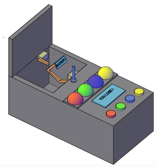
Our CAD Drawings helped us visualize and improve our design as we went deeper in to planning. The base design of our Simon Says Box is largely inspired by the “Useless Box” as shown. This includes the way the lid is placed and where the arms are able to come out. However, we designed a larger room of space to mount the buttons, LEDs, and LCD screen. We decided to 3D print our entire design except for the functioning components such as buttons, LEDs, LCD and servo motors. The components that were 3D printed are the box itself, the lid, the hinge (all items in dark grey), servo motor casings (light grey), the arms for the servos (depicted in orange). and the sign (light blue). The LEDs were covered by ping pong balls cut in half in order to display a cleaner finish and a wider range of visible light.
Source: SIMON SAYS BOX
- How does the player lose the game?
The player loses if they fail to press the correct button within three seconds or if they press an incorrect button. - What happens during the losing sequence?
All lights blink three times, the LCD displays YOU LOSE!, and servo motors reveal a Sucker sign before resetting. - What is the maximum number of levels in the game?
The game is programmed to go up to 100 levels, making it nearly impossible to beat. - How are the LEDs powered relative to the Arduino?
The Arduino regulates six volts from the battery pack down to five volts for the arcade buttons and LEDs operate at three volts. - Which pins connect the LCD screen to the Arduino?
The I2C LCD screen connects to the A4 and A5 analog pins of the Arduino. - What visual effect is used for the greeting messages on the LCD?
A scrolling effect shifts the introduction words toward the left side of the LCD screen. - Why is there no winning sequence designed?
Passing level 100 is highly improbable, so the system transitions to the losing sequence even if reached. - What material covers the LEDs for a cleaner finish?
Cut ping pong balls are placed over the LEDs to display a wider range of visible light.