Summary of Shift Register Keyboard for Arduino
This article details a DIY project to expand an Arduino's input capacity using shift registers, enabling up to 4096 button inputs with only four IO pins. The system utilizes a CD4021BE for data input and two SN74HC595 registers for output, wired in a matrix configuration. The guide covers circuit design, code troubleshooting involving clock pulses, PCB soldering, 3D printing the enclosure, and final assembly into a functional keyboard.
Parts used in the Shift Register Keyboard:
- Arduino
- 30 tact switches
- PCB
- CD4021BE shift register
- SN74Hc595 shift register (x2)
- LEDs (for debugging)
- Sockets for chips
- Header pins
- Molex connector
- Ethernet cable wire
- Resistor leads
- 3mm screws and nuts
- Super glue
A common problem that often comes up when working with micro controllers, is running out of IO for all the input the projects requires. So I came up with this solution that allows a user to have up to 4096 button inputs using only 4 lines of IO. This is done by sending out data with a SN74Hc595 shift register, and reading data from a CD4021BE.
Supplies
1- Arduino
30- tact switches
1- PCB
1- CD4021BE shift register
2- SN74Hc595 shift register
Step 1: How It Works
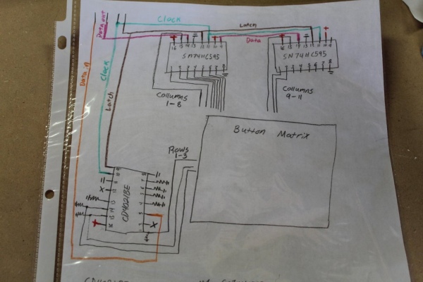
The hart of this keyboard is 3 shift registers. Two 74HC595 and one CD4021BE. which are wired to a 10X3 button matrix. Pin 15 of the first 74HC595 is turned high. This connects every button in the first column to positive 5V. If any of the three buttons in the first column are pressed it sets the corresponding pin on the CD4021BE high. Then the data from the CD4021BE is shifted in. So at this point the Arduino knows which column was high at the time and which row went high. This information gives us the coordinates of the button that was pressed. The CD4021BE is then reset and the next output pin is pulsed high.
Only four IO pins of the Arduino are used.
Latch – shared by all shift registers
Clock – shared by all shift registers
DataOut – bits that are shifted out. 74HC595 only
DataIn – bits that are shifted in. CD4021BE only
The most useful application that I could think of off the top of my head, that uses this, was a keyboard. Obviously this has only 30 input and not the stated 4096. However this method can easily be expanded by adding more shift registers. You can daisy chain 8 shift registers together. Each shift register has 8 pins that shift out or in. So if there where 8 shift registers shifting in and 8 shifting out, that gives us (8*8)^2 = 4096 total inputs while still using just 4 IO.
Step 2: Building the Board
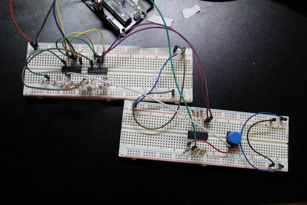
Like most electronic projects this one started on a bread board. Before I started plugging things in I had drew a schematic to go off of. I have had some experience working with shift registers and with just a little bit of googling, I drew the final working schematic on the very first try. I had every pin on the 74HC595 shift registers attached to an LED. This made it very easy for trouble shooting, to be able to see which pin on the on the shift register was high at any given moment, At this stage I only needed one button hooked up and just moved a jumper around to test the pin on the CD4021BE
Step 3: Writing the Code
For the most part the writing of the code was fairly easy. All it really does is turn one column high, then checks the row to see if a button was pressed completing a circuit. From that data it knows the row and the column of a pressed button. The row and column values are then plugged into a 2 decimal array which then spits out the letter on the keyboard.
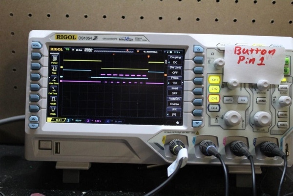
I only had one major problem when writing this code. It was with the shifting of the data on the CD4021BE. When I was testing the inputs I found that one of the pins was not returning any value and the others that were returning a value, it was one bit too high. So if the value of pin7 was supposed to be 1 (00000001) it would become 2 (00000010). while pin1 (10000000) would just be pushed out. I went online but was not able to find anything that helped. So I hooked the board up to the oscilloscope to do some investigating. What was happening was every input was being shifted up one bit. This was because the clock pulses where missing the first input and pulsing at the end where no input would be.
SOLUTION: You need to set clockPin high before pulling latch low then shiftIn, then latch high.
Step 4: Soldering the Board
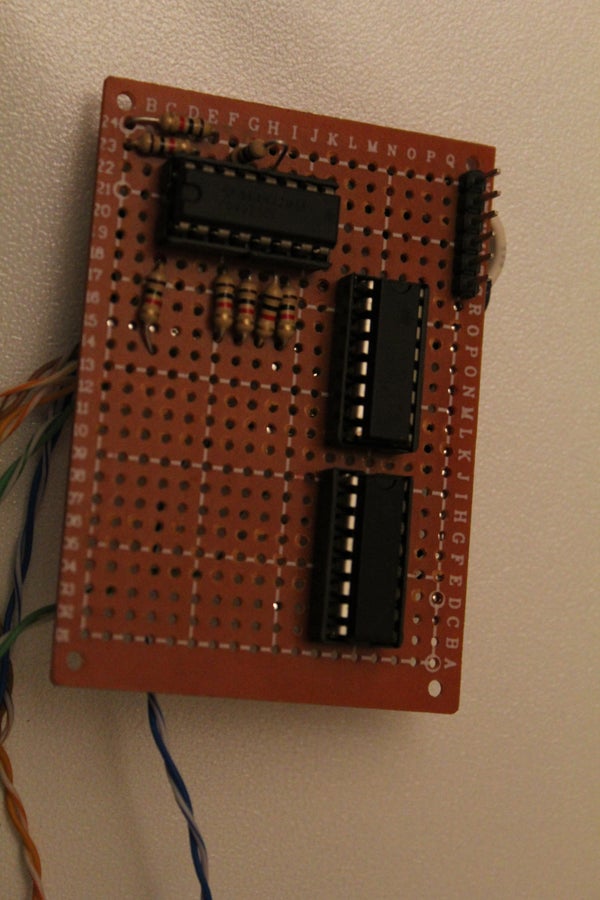
Now that we know the circuit works it needs to be transferred to a permanent board. this isn’t hard it just takes time. I use sockets for the chips just incase I screw up I don’t have to desolder anything. I can just start over. But if you plan on using sockets just know that It means your board is going to take up a lot more vertical space. Also I used header pins for the power and IO connectors so it would not be hard wired to anything and can be easily taken apart.
Step 5: Building the Button Matrix
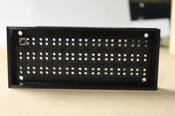
Instead of soldering tact switches to a PCB, I opted to print a box for the tact switches and super glue them in place. Printing the box made it easy to get the switches exactly where I wanted them and made mounting it inside the case a breeze. For all the wiring I just solder directly to the leads of the switches. I soldered the rows using left over leads of resistors, and the columns are connected with wire I got from some old Ethernet cable. Then each row is wired to the CD4021BE and each column is wired to the 74HC595.
Step 6: 3D Printing the Enclosure
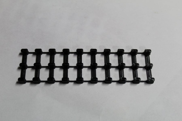
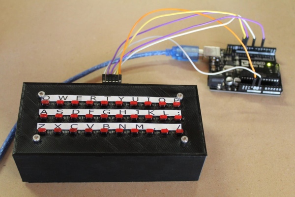
The whole body of the keyboard was drawn up in fusion 360 and 3D printed on my Ender3 . To make the keyboard stand out a little bit more I spray painted the button caps red. Once the circuit board is inside the enclosure you will no longer be able to access the header pins. So I made a header pin bracket. 6 header pins are glued to the bracket and wires connected to header pins are soldered to the back of the headers. Then the bracket is super glued to the outside enclosure.
Step 7: Final Assembly
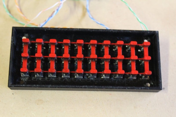
At this point the only thing left to do is put the whole thing together. The button caps are placed over the tact switches than the face plate a placed over top. Four 3mm screws and nuts are used to hold the face plate tight to the button box. Once done, to Molex connector coming off the the header pin plug is attached to the headers on the circuit board. The circuit board is than placed into the box. Than the button assembly is attached to the top. Last came the lettering. Now there are definitely better ways of doing the lettering but, the way I did it was by typing out the lines in inscape and making sure that they were the right size. Than cut them out and supper glued into place.
Step 8: Final Thoughts
I am really happy with how this came out. The only thing that I don’t like about it is how thick it is. But that can be solved by not using sockets for the chips and taking a bit more time planning out the lay out. There are a ton of ideas I have for products that require a keyboard of a large number of user inputs and this was a great step forward towards building them. I hope some of you have found this page useful or interesting and thank you so much for reading.
Read more: Shift Register Keyboard for Arduino
- How many IO lines are required for this project?
Only four IO pins of the Arduino are used. - What is the maximum number of button inputs this method can support?
This method can support up to 4096 total inputs by daisy chaining eight shift registers together. - Which specific shift registers are used in the heart of this keyboard?
The project uses two 74HC595 shift registers and one CD4021BE shift register. - How does the system determine which button was pressed?
It turns one column high to check rows; knowing the active column and row provides the coordinates of the pressed button. - What was the specific issue found during code testing?
Every input was being shifted up one bit because clock pulses missed the first input and pulsed at the end where no input existed. - What is the solution to the shifting problem described in the article?
You need to set the clock pin high before pulling the latch low, then shiftIn, and finally set the latch high. - Why were sockets used for the chips during construction?
Sockets were used so that if the builder makes a mistake, they do not have to desolder anything and can just start over. - How were the columns connected in the button matrix wiring?
The columns are connected with wire obtained from some old Ethernet cable. - What software was used to create the enclosure design?
The whole body of the keyboard was drawn up in fusion 360.