Summary of Servo Position Control with Weight (Force Sensor)
This tutorial outlines a project to control a servo motor's shaft position based on weight detected by an FSR400 force sensor. The system utilizes an Arduino Uno to read the sensor's resistance changes via its 8-bit ADC and converts them into PWM signals to adjust the servo angle. The article details the wiring of servo wires (Red, Black, Yellow), the specific operating principles of the FSR400 regarding pressure and resistance, and the use of a voltage divider circuit to translate these resistance changes into readable voltage levels for the microcontroller.
Parts used in Servo Control System with Force Sensor:
- Force sensor (FSR400)
- Arduino Uno
- Servo motor
- Voltage divider circuit
- Constant resistance resistor
- Connecting wires
In this tutorial we will develop a circuit using Force sensor, Arduino Uno and a servo motor. It will be a servo control system where the servo shaft position is determined by the weight present on the force sensor. Before going any further let’s talk about about the servo and other components.
Servo Motors are used where there is a need for accurate shaft movement or position. These are not proposed for high speed applications. These are proposed for low speed, medium torque and accurate position application. These motors are used in robotic arm machines, flight controls and control systems. Servo motors are also used in some of printers and fax machines.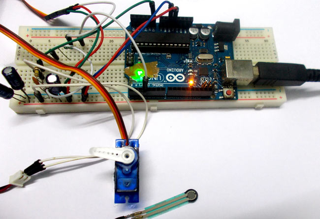
Servo motors are available at different shapes and sizes. A servo motor will have mainly there wires, one is for positive voltage another is for ground and last one is for position setting. The RED wire is connected to power, Black wire is connected to ground and YELLOW wire is connected to signal.
A servo motor is a combination of DC motor, position control system, gears. The position of the shaft of the DC motor is adjusted by the control electronics in the servo, based on the duty ratio of the PWM signal the SIGNAL pin. Simply speaking the control electronics adjust shaft position by controlling DC motor. This data regarding position of shaft is sent through the SIGNAL pin. The position data to the control should be sent in the form of PWM signal through the Signal pin of servo motor.
The frequency of PWM (Pulse Width Modulated) signal can vary based on type of servo motor. The important thing here is the DUTY RATIO of the PWM signal. Based on this DUTY RATION the control electronics adjust the shaft.
As shown in below figure, for the shaft to be moved to 9o clock the TURN ON RATION must be 1/18.ie. 1milli second of ‘ON time’ and 17milli second of ‘OFF time’ in a 18ms signal.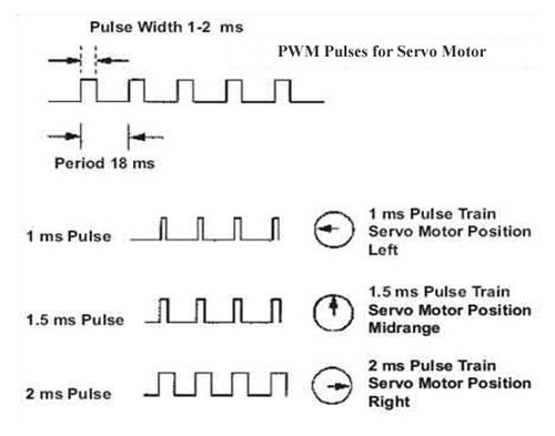
For the shaft to be moved to 12o clock the ON time of signal must be 1.5ms and OFF time should be 16.5ms.
This ratio is decoded by control system in servo and it adjusts the position based on it.
This PWM in here is generated by using ARDUINO UNO.
So for now we know that, we can control the SERVO MOTOR shaft by varying the duty ratio of PWM signal generated by UNO.
Now let’s talk about force sensor or weight sensor.
To interface a FORCE sensor with ARDUINO UNO, we are going use 8 bit ADC (Analog to Digital Conversion) feature in arduno uno.
A FORCE sensor is a transducer which changes its resistance when pressure is applied on surface. FORCE sensor is available in different sizes and shapes.
We are going to use one of the cheaper versions because we don’t need much of accuracy here. FSR400 is one of the cheapest force sensors in the market. The picture of FSR400 is shown in below figure.
Now it is important to note that the FSR 400 is sensitive along the length, the force or weight should be concentrated on the maze on the middle of eye of sensor, as shown in figure.
If the force is applied at wrong times the device could damage permanently.
Another important thing to know that, the sensor can drive currents of high range. So keep in mind the driving currents while installing. Also the sensor has a limit on force that is 10Newtons. So we can apply only 1Kg of weight. If weights higher than 1Kg applied the sensor might show some deviations. If it’s increased more than 3Kg. the sensor might damage permanently.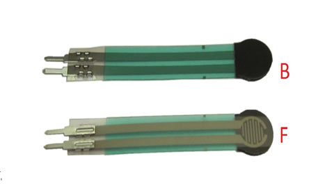 As told earlier this sensor is used to sense the changes in pressure. So when the weight is applied on top of FORCE sensor, the resistance is changed drastically. The resistance of FS400 over weight is shown in below graph:
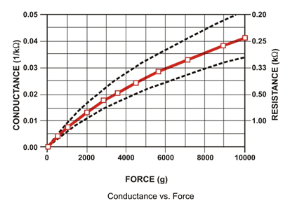
As shown in above figure, the resistance between the two contacts of sensor decreases with weight or the conductance between two contacts of sensor increases.
The resistance of a pure conductor is given by:

Where,
p- Resistivity of conductor
l= Length of conductor
A= Area of conductor.
Now consider a conductor with resistance “R”, if some pressure is applied on top of conductor, the area on conductor decreases and the length of conductor increases as a result of pressure. So by formula the resistance of conductor should increase, as the resistance R is inversely proportional to area and also directly proportional to length l.
So with this for a conductor under pressure or weight the resistance of conductor increases. But this change is small compared to overall resistance. For a considerable change many conductors are stacked together.
This is what happens inside the Force Sensors shown in above figure. On looking closely one can sees many lines inside the sensor. Each of these lines represents a conductor. Sensitivity of sensor is in conductor numbers.
But in this case the resistance will be decreasing with pressure because the material used here is not a pure conductor. The FSR here are robust polymer thick film (PTF) devices. So these are not pure conductor material devices. These are made up of a material, that exhibit a decrease in resistance with increase in force applied to the surface of the sensor.
This material shows characteristics as shown in graph of FSR.
This change in resistance can do no good unless we can read them. The controller at hand can only read the chances in voltage and nothing less, for this we are going to use voltage divider circuit, with that we can derive the resistance change as voltage change.
Voltage divider is a resistive circuit and is shown in figure. In this resistive network we have one constant resistance and other variable resistance. As shown in figure, R1 here is a constant resistance and R2 is FORCE sensor which acts as a resistance.
Read More: Servo Position Control with Weight (Force Sensor)
- How is the servo motor shaft position determined?
The shaft position is determined by the weight present on the force sensor. - What are the three wires of a servo motor and their functions?
The RED wire connects to power, the BLACK wire to ground, and the YELLOW wire to the signal pin. - How does the Arduino control the servo motor?
The Arduino generates a PWM signal where the duty ratio adjusts the shaft position. - What happens to the resistance of the FSR400 when weight is applied?
The resistance decreases while conductance increases as pressure or weight is applied. - Can the FSR400 handle weights higher than 1Kg?
Weights higher than 1Kg may cause deviations, and weights over 3Kg can permanently damage the sensor. - Why is a voltage divider circuit used in this project?
A voltage divider converts the change in resistance from the force sensor into a change in voltage that the controller can read. - What type of material is the FSR400 made of?
The FSR400 is a robust polymer thick film device that exhibits decreased resistance with increased force. - Where should force be concentrated on the FSR400 sensor?
Force should be concentrated on the maze in the middle of the eye of the sensor to avoid damage.