
Summary of Serial LCD Module
This article describes a project to convert a standard 16×2 alphanumeric LCD into a serial interface module using an ATmega8 microcontroller. This design reduces pin usage on the main controller, operates at a 9600 baud rate, and allows for backlight control. The system uses Arduino Uno as the host and features an 8MHz internal oscillator to save hardware components while maintaining compatibility with various AVR chips like ATmega168 or 328.
Parts used in the Serial LCD Module:
- 16×2 Alphanumeric LCD Display
- ATmega8 Microcontroller (IC1)
- Arduino Uno Board
- Single-side PCB
- IC Base
- USB Cable
In most electronic systems, it is necessary to provide information in the visual form for a convenient user interface. The most commonly used displays in electronic systems are LED, LCD and TFT. Amongst these, an LCD display is the most cost-effective solution as it can display alphanumeric characters along with special user-defined symbols. It also contains an integrated controller which frees up the main microprocessor from the task of refreshing the display and improves overall system throughput. But at the same time it requires a large number of pins for interfacing with the system, which consume a lot of microcontroller’s ports.
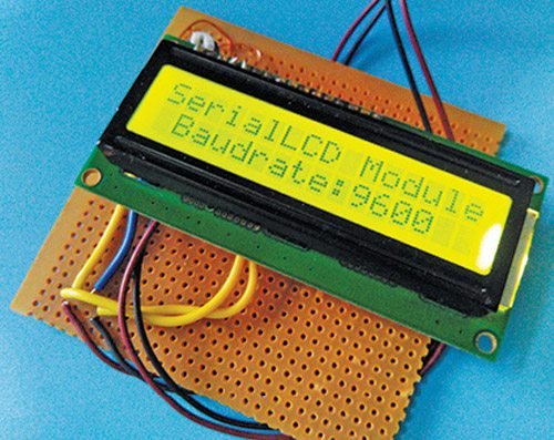
Author’s prototype
The presented serial LCD module can convert any 16×2 alphanumeric LCD display to a serial LCD which communicates with the main controller using serial communication technique. The brightness of LCD backlight can also be controlled. If the text exceeds 16 characters, the remaining text automatically accommodates in the second line. The serial LCD module communicates on 9600 standard baud rate, which is compatible with all microcontrollers. Fig. 1 shows the author’s prototype of the serial LCD module.
Circuit and working
Fig. 2 shows the circuit of the serial LCD module connected to Arduino Uno (Board1)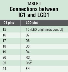 using only one wire. Microcontroller ATmega8 (IC1) works with an 8MHz internal oscillator. It uses no-xtal bootloader which provides Arduino compatibility without 16MHz external crystal. Using 8MHz internal oscillator reduces hardware and improves power efficiency. IC1 uses its serial port to communicate with the main controller (Arduino Uno in this case). It acts as a bridge between the main controller and the LCD.
ATmega8 can be replaced by ATmega168/328 without changing the code, but the bootloader will need to be changed. Table I indicates the connections between IC1 and LCD1. The supply to the module is provided by the Arduino Uno itself as shown in Fig. 2.
Arduino Uno board. Arduino is an open source electronics prototyping platform based on flexible, easy-to-use hardware and software. It is intended for artists, designers, hobbyists and anyone interested in creating interactive objects or environments. Arduino Uno is a board based on ATmega328 microcontroller. It comprises 14 digital input/output (I/O) pins, six analogue inputs, a USB connection for programming the on-board microcontroller, power jack, an ICSP header and a reset button. It is operated with a 16MHz crystal oscillator and contains everything needed to support the microcontroller. It is very easy to use as the user simply needs to connect it to a computer with a USB cable or power it with an AC-to-DC adaptor or battery to get started. The microcontroller on the board is programmed using Arduino programming language and Arduino development environment.
Software
The software for the serial LCD module is written in Arduino programming language. Follow the steps below to burn the bootloader and the firmware in IC1:
1. All the required software is provided in EFY DVD and at source.efymag.com. Put the ATmega8 (IC1) chip in Arduino Uno board and follow the instructions: click here. The fuse bits are 0xCA and 0xD4. Program lock bits as 0x0F so that the bootloader is not overwritten every time you flash new firmware.
2. Edit board file (arduino-0022/hardware/arduino/boards.txt) by adding the lines:
[stextbox id=”grey”]
atmega8noxtal.name=ATmega8-noxtal @8MHz
atmega8noxtal.upload.protocol=stk500
atmega8noxtal.upload.maximum_size=7168
atmega8noxtal.upload.speed=38400
atmega8noxtal.bootloader.low_fuses=0xd4
atmega8noxtal.bootloader.high_fuses=0xca
atmega8noxtal.bootloader.path=atmega8_noxtal
atmega8noxtal.bootloader.file=ATmegaBOOT.hex
atmega8noxtal.bootloader.unlock_bits=0x3F
atmega8noxtal.bootloader.lock_bits=0x0F
atmega8noxtal.build.mcu=atmega8
atmega8noxtal.build.f_cpu=8000000L
atmega8noxtal.build.core=arduino
atmega8noxtal.build.variant=standard
3. Restart Arduino IDE (Arduino-0022) and you will see a new entry (ATmega8-noxtal@8MHz) in the ‘Boards’ menu. Copy the provided code in Arduino IDE and select board as atmega8-noxal.

Circuit diagram of serial LCD module
4. Go to File→Upload to program the sketch in IC1.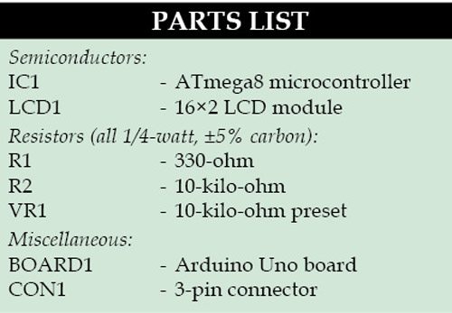
5. Remove ATmega8 chip from the Uno board and
place back the original microcontroller. Put the programmed ATmega8 chip in the provided PCB and your serial LCD module is ready to use. If you wish to use ATmega168/328, you must choose proper bootloader and board before uploading. Sketch is compatible with all these microcontrollers.
You can use serial LCD library if you want to drive the serial LCD module using Arduino Uno. For that, connect the board with the module as shown in Fig. 2 and copy the library (serialLCD) to the libraries folder of Arduino IDE.
You can use lcd.backLight( ); function to control the brightness of LCD.
Construction and testing
An actual-size, single-side PCB for serial LCD module is shown in Fig. 3 and its component layout in Fig. 4. Assemble the circuit on the recommended PCB to minimise any assembly errors. Use IC base for ATmega8.
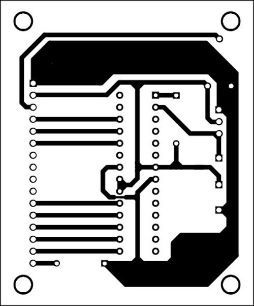
An actual-size, single-side PCB for the serial LCD module
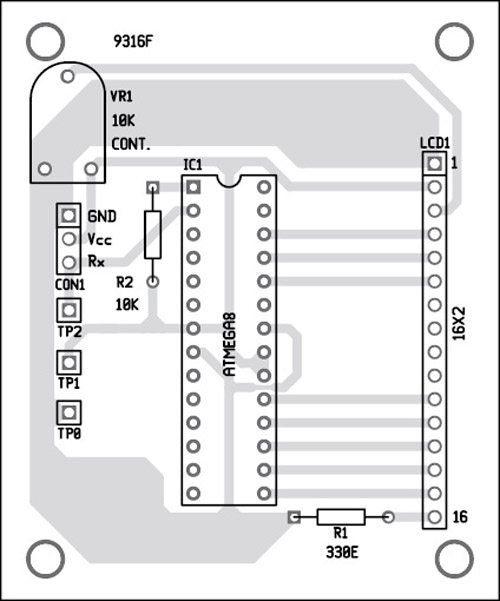
Component layout for the PCB
Download the PCB and Layout PDF: click Here
Download Source Code: Click Here
To test the circuit for proper functioning, verify correct 5V supply at TP1 with respect to TP0. The serial data to the LCD module can be seen at TP2 using an oscilloscope.
Read More Detail :Serial LCD Module
- How does this project improve system throughput?
The integrated controller frees up the main microprocessor from refreshing the display. - What is the communication speed of the module?
The module communicates at a standard 9600 baud rate. - Can the backlight brightness be adjusted?
Yes, the brightness can be controlled using the lcd.backLight function. - Does the module require an external crystal oscillator?
No, it uses an 8MHz internal oscillator to reduce hardware requirements. - Which microcontrollers are compatible with the code?
The sketch is compatible with ATmega8, ATmega168, and ATmega328. - How many wires are needed to connect the module to the Arduino Uno?
The circuit connects using only one wire for data communication. - What happens if text exceeds 16 characters?
The remaining text automatically accommodates in the second line. - Where can the source code and PCB layout be downloaded?
They are available via the provided links on the EFY website.