
Summary of Serial Communications with Arduino
This article explains how to monitor and control a robot's decision-making process using Arduino serial communication. It details the binary system (bits and bytes) used for data transmission and provides code examples to read sensor values via the Serial Monitor. The goal is to gauge intelligence, adjust variables, and improve efficiency by observing real-time data output from analog pins.
Parts used in the Robot Intelligence Monitoring Project:
- Arduino
- Sensors
- Analog Pin 0
- Serial Monitor
At this point you should have a robot that can think on its own, we need to be able to tap into its thought process. See what he sees. Make some of his decisions for him. in essence, we need to be able to guage his intelligence to make him more intelligent and increase his efficiency.
With serial communications we can do two things: We can either send commands or receive data. Here are some examples to
use with Serial communications:
1. Find out what values your sensors are outputting.
2. Find out if your robot is making the right decisions (Drugs = FALSE;)
3. Change the value of a variable.
4. Control your robot’s movement or other things in your robot
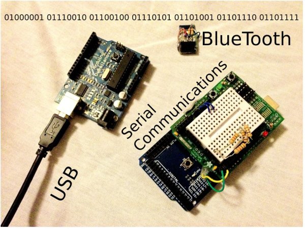
Step 1: A BIT of information.
Serial communication works on 1s and 0s. Also known as binary, the Arduino sends these 1s and 0s (bits) one by one, or Serially. These bits are sent in the form of Highs(1) and Lows(0). These bits form together and turn into bytes. A byte is composed of 8 bits. Here’s a little tutorial on binary:
Each bit represents a certain number to add. the first bit (Far right) represents the ones place, similar to the common decimal system.
1 = 1 and 0 = 0.
the next bit’s value is multiplied by two, so:
10 = 2, 11 = 3, 00 = 0 and 01 = 1.
similarly:
100 = 4,
1000 = 8,
10000 = 16,
100000 = 32,
1000000 = 64
10000000 = 128.
Now these bits can form a value up to 255 (11111111).
This value can be turned into ASCII encoded symbols and letters. Here’s a list of them.
Step 2: Serial Output Code
void setup (){
Serial.begin(9600);
}

void loop(){
Serial.print("The analog value is: ");
Serial.println(analogRead(A0));
delay(100);
}
Serial Print is a function that prints whatever you specify on the Serial Monitor. In this code, we are going to print the analog value of whatever is in Analog Pin 0.
In the void setup, we begin the serial monitor at a baud rate of 9600.
In the void loop, we are using the Serial.println function and what we are printing is the value found in A0 by the Analog Read.
For more detail: Serial Communications with Arduino
-
What is the primary purpose of serial communication in this project?
To send commands or receive data to gauge the robot's intelligence, observe its decisions, and increase efficiency. -
How does serial communication transmit data?
It works on 1s and 0s known as binary, sending bits one by one in the form of Highs(1) and Lows(0). -
How many bits make up a single byte?
A byte is composed of 8 bits. -
What baud rate is used to begin the serial monitor in the provided code?
The serial monitor begins at a baud rate of 9600. -
Which function prints the analog value from pin A0 in the example code?
The Serial.println function is used to print the value found in Analog Pin 0. -
Can you change variable values using serial communication?
Yes, serial communication allows you to change the value of a variable. -
What is the maximum decimal value a byte can represent?
The maximum value a byte can turn into is 255.
