
Summary of Serial Basic Hookup Guide
The Serial Basic is a cost-effective USB-to-Serial adapter utilizing the CH340G IC, compatible with 3.3V and 5V systems. It features auto-install drivers, a voltage selection jumper, and TX/RX LEDs for monitoring traffic. Designed to work seamlessly with devices like Arduino Pro Mini and GPS modules, it supports standard DTR/RX/TX/VCC/CTS/GND pinouts. The board includes alignment markers and can be tested via a simple loop-back method using a terminal program.
Parts used in the Serial Basic:
- CH340G IC
- DTR Pin
- RXI Pin
- TXO Pin
- VCC Pin
- CTS Pin
- GND Pin
- GRN Indicator
- BLK Indicator
- Voltage Selection Jumper
- Green LED (TX)
- Yellow LED (RX)
- A to micro-B USB Cable
Introduction
The Serial Basic is an easy to use USB to Serial adapter based on the CH340G IC from WCH. It works with 5V and 3.3V systems and should auto install on most operating systems without the need for additional drivers. It’s a great lower cost option to the extremely popular FTDI Basic.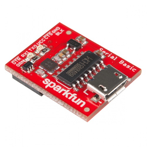
The Serial Basic uses the CH340G IC to quickly and easily convert serial signals to USB. It works great with all of our products including the Arduino Pro Mini, our GPS modules, cellular modules, and many other devices that uses serial communication.
Suggested Reading
This is an easy board to get started with, but, if you are not sure how serial works or have not used a terminal program before, you may want to checkout the following tutorials.
Serial Basic Overview
The pinout of the Serial Basic mimics the common DTR/RX/TX/VCC/CTS/GND pinout found on hundreds of FTDI-to-USB derivatives.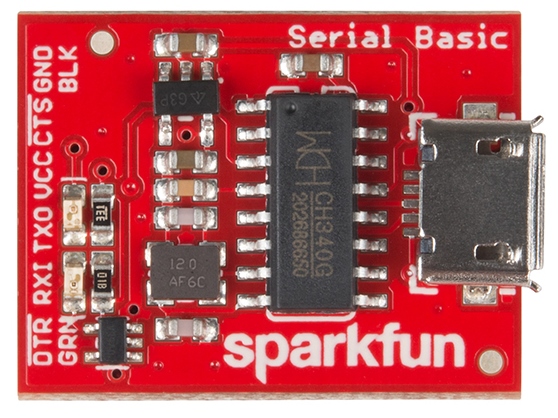
| Pin Label | Input/Output | Description |
|---|---|---|
| DTR | Output | Data Terminal Ready, Active Low |
| RXI | Input | Serial Receive |
| TXO | Output | Serial Transmit |
| VCC | Supply Output | Power supply 3.3V or 5V |
| CTS | Input | Clear To Send, Active Low |
| GND | Supply Output | Ground (0V) supply |
Alignment Markers
These GRN and BLK indicators are there to help you align the board properly with products that use this same pinout.
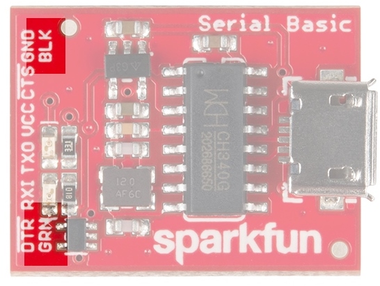 The Serial Basic mates seamlessly with products that use the standard serial connection. If you see a board with the
 BLK and GRN labels, then you know it will be compatible with the Serial Basic.
Voltage Selection Jumper
There is a jumper on the rear of the board that controls the output voltage on the VCC pin. By default, the board outputs 3.3V and has 3.3V signals. Changing this jumper to 5V will cause the board to output 5V on the VCC pin with 5V signals.
When the jumper is set to 3.3V, the board uses an onboard 3.3V regulator capable of sourcing 600mA. If you attempt to pull more than 600mA, the regulator will go into short-circuit shutdown where it will only output 150mA.
When the jumper is set to 5V, the board will source as much power as your USB port will provide.
LEDs
There are two LEDs on the board connected to TX (Green) and RX (Yellow). This is a quick and handy way to see the serial traffic.
Hardware Test
To connect the board to a computer, you will need a standard A to micro-B USB cable. Plug the micro-B USB cable into a USB port on your computer and the other end into the Serial Basic. Your computer should automatically install the necessary drivers and create a COM port on your computer. If you are prompted for drivers, please see the Installing Drivers section.
The quickest and easiest way to make sure everything is working is to do a TX/RX loop-back. To do this, insert a jumper wire between TX and RX. Anything that is transmitted from the TX pin will be echoed back to the RX pin.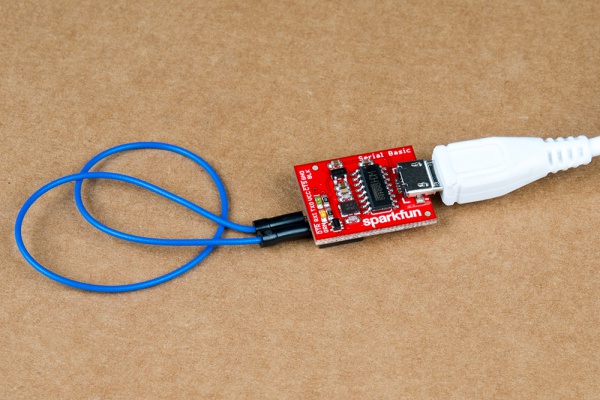
Open your favorite terminal program. Select the COM port that the Serial Basic is assigned to, and connect. When you type a character, you should see each character you type echoed back in the terminal.
Read More: Serial Basic Hookup Guide
- What chip does the Serial Basic use?
The board uses the CH340G IC from WCH. - How do I change the output voltage on the VCC pin?
There is a jumper on the rear of the board that controls the output voltage between 3.3V and 5V. - Can the Serial Basic work without installing additional drivers?
Yes, it should auto install on most operating systems without the need for additional drivers. - What is the maximum current the onboard 3.3V regulator can source?
The regulator is capable of sourcing 600mA when the jumper is set to 3.3V. - How can I verify the board is working correctly?
You can perform a TX/RX loop-back by inserting a jumper wire between TX and RX and checking for echoed characters in a terminal program. - Which cables are needed to connect the board to a computer?
You will need a standard A to micro-B USB cable. - What do the GRN and BLK indicators indicate?
These alignment markers help you align the board properly with products that use the same pinout. - What happens if I pull more than 600mA while the jumper is set to 3.3V?
The regulator will go into short-circuit shutdown where it will only output 150mA. - Does the board support both 3.3V and 5V systems?
Yes, the Serial Basic works with 5V and 3.3V systems.
