
Summary of Arduino-Powered Water Bottle
This article details the construction of a smart water bottle using an Arduino to track daily and weekly intake, remind users to drink water, monitor last intake time, and operate for over a month on a single charge. The project addresses chronic dehydration by automating hydration tracking through a custom-built Real-Time Clock (RTC) module and a multiplexed 7-segment display, ensuring accurate logging even when the device is in sleep mode.
Parts used in the Smart Water Bottle:
- Arduino Microcontroller
- DS1307 RTC Chip (or DS3231)
- External Crystal Oscillator (required for DS1307)
- Pull-up Resistors (4.7k Ohm for SCL/SDA)
- 4-Digit Common-Cathode 7-Segment Display
- Four 2N2222 NPN Transistors
- Current-Limiting Resistors (1K Ohm and 220R Ohm)
- Button Switch
- Li-ion Battery
- Connecting Wires
Introduction:
Drinking enough water is very important for our health. Drinking more water can lead to clearer skin, better overall health, improved productivity and brain function, increased energy levels, and even weight loss.
In our busy lives, it is really hard to remember to drink enough water. And most of the time we forget to drink enough water whether we are in the home, office or on-the-go. Around 75% of Americans are chronically dehydrated all the time.
So, in order to build a healthy water drinking habit, it’s important to track your water intake every day.
To track my water intake I made my water bottle smart using Arduino. It can:
1. Track my daily water intake
2. Track my weekly average water intake
3. Remind me to take water
4. Track last intake time
5. Run more than one month in a single charge.
Making RTC Module
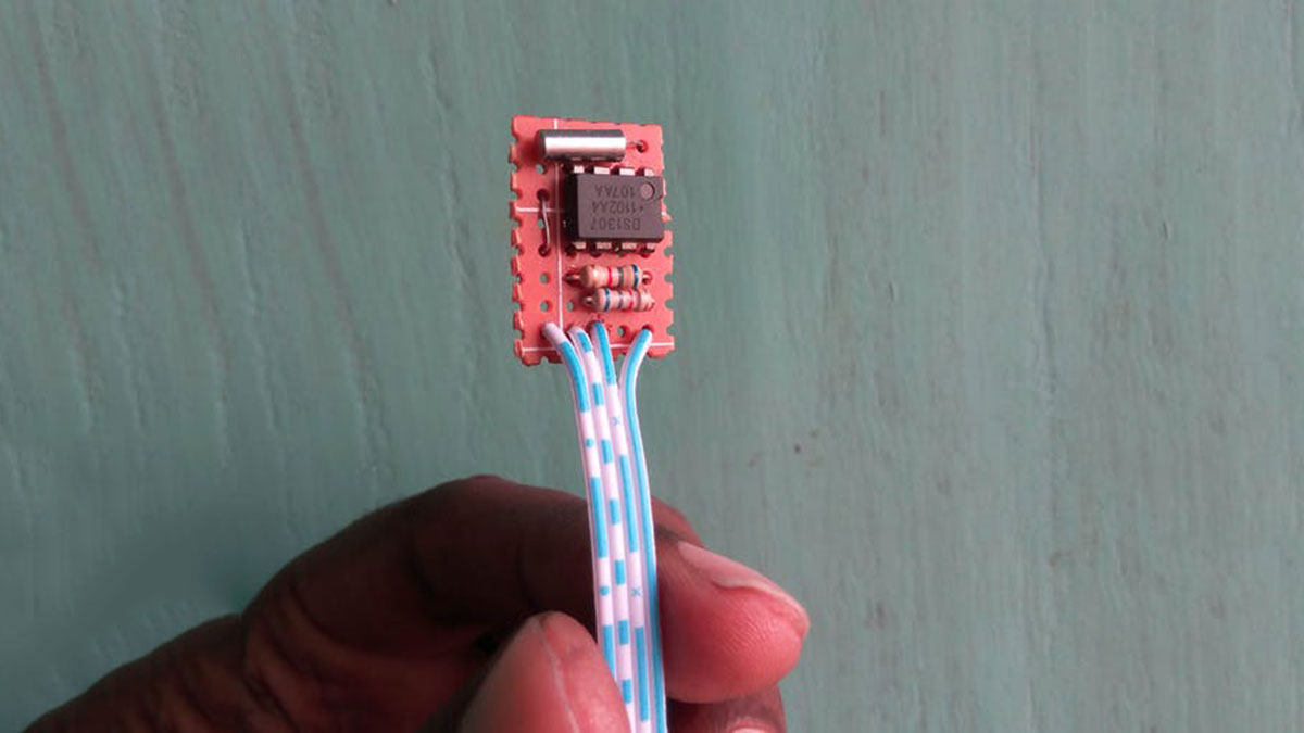
To log or track water intake information, it requires current time and date information to be stored along with the accumulated data. A Real-Time Clock (RTC) chip such as DS1307 with a suitable back-up battery can be used to supply the required information. The programming process of the RTC chip (in software) is also very simple and is supported in the majority of programming environments.
Here is the design of a compact RTC module, based on the popular RTC IC DS1307, for your everyday microcontroller projects. The DS1307 serial real-time clock (RTC) is a low power, full binary coded decimal (BCD) clock/calendar plus 56 bytes of NV SRAM. Address and data are transferred serially through an I2C, bidirectional bus. The 24-hour/12-hour format clock/calendar provides seconds, minutes, hours, day, date, month, and year information, including corrections for leap year.
Let’s make the real time clock module according to the attached schematic. DS1307 RTC requires an external crystal to operate correctly. Two pull-up resistors are required for SCL & SDA pin of the IC. The value of the resistor may be around 2k to 10k. I used 4.7k. During soldering I tried to keep the module as small as possible because space is limited for my circuit. You can use DS3231 instead of DS1307 and the IC has an internal crystal oscillator. So, you need not to add any external crystal. You may also buy a ready-made tiny RTC module if you don’t like to make it own. As the complete system will be operate from battery, for that reason I connected VBAT pin of the RTC to ground without using coin cell.
Important Pins of DS1307:
- 5V Pin: When this pin is high, then the ds1307 sends the data, and when it is low, it runs on the backup button cell.
- GND: This is the ground pin for the module. Both the ground of the battery and the power supply are tied together.
- SCL: It is the I2C clock pin – which communicates with the microcontroller. Should connect with Arduino SCL pin.
- SDA: It is the I2C data pin – which communicates with the microcontroller. Should connect with Arduino SDA pin.
- VBAT: Battery input for any standard 3V lithium cell or other energy source. Must be grounded if not used.
Making Seven Segment Display Board
For the display module here I used a self-contained, compact common-cathode module containing four 7-segment LED numeric displays good for displaying numerical data with some simple character.
Each segment in the display module is multiplexed, meaning it shares the same anode connection points. And each of the four digits in the module have their own common cathode connection point. This allows each digit to be turned on or off independently. Also, this multiplexing technique turns the massive amount of microcontroller pins necessary to control a display into just eleven or twelve (in place of thirty-two)!
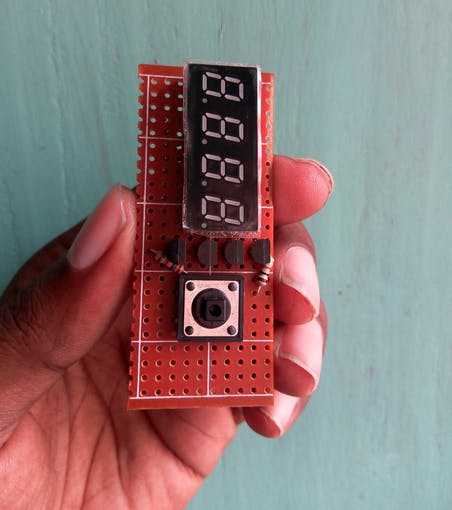
The LED segments of the display require current-limiting resistors when powered from a 5 V logic pin. The value of the resistor is typically between 330 and 470 ohms for 5 V. For Li-ion battery operation it may be 220 ohms. And, driver transistors are recommended to provide additional driving current to the LED segments, because each pin of a microcontroller can source or sink near 40 mA of current only. When all (seven) segments of the display turned on at once (the numeral 8), the current demand will exceed this 40 mA limit. The image shown below indicates the basic wiring diagram of the current limiting resistors and driver transistors.
This 4 -digit 7-segment display section is wired around four common-cathode 7-segment LED displays, and four 2N2222 NPN transistors. The 1K resistors are used for base current limiting, and the 220R resistors limits the operating current of the LED display segments.
In the Arduino board, digital outputs from D10 to D17 are used to drive segments (a to g & dp), and digital outputs D6 to D9 are used for the digits (D0-D3) of the 4×7 LED display.
A button switch is added with the display module to access different options. It will also used to wake up the Arduino from sleep mode using external hardware interrupt. so, button is connected to Arduino digital pin #2 (INT0).
-
Why is it important to track water intake?
Tracking helps build healthy habits because around 75% of Americans are chronically dehydrated and often forget to drink enough water. -
How does the project track the current time?
It uses a Real-Time Clock chip like the DS1307 with a backup battery to store date and time information for logging data. -
What is the purpose of the pull-up resistors in the RTC circuit?
Two pull-up resistors are required for the SCL and SDA pins of the IC, typically valued between 2k to 10k ohms. -
Can I use a DS3231 instead of the DS1307?
Yes, you can use a DS3231 which has an internal crystal oscillator, so you do not need to add any external crystal. -
Why are driver transistors recommended for the display?
Transistors provide additional driving current because a microcontroller pin can only source or sink near 40 mA, which is exceeded when all segments turn on. -
Which Arduino pins are used to drive the 7-segment display segments?
Digital outputs from D10 to D17 are used to drive the segments (a to g and dp). -
How does the button switch function in this project?
The button allows access to different options and wakes up the Arduino from sleep mode using an external hardware interrupt on pin #2.
