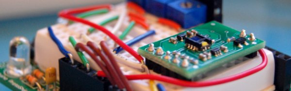
About 2 years ago I picked up a ADJD-S371 color sensor from Sparkfun to work with my arduino. I spent a few days getting it to work, but finally got it going pretty well. I still get a few emails here and there asking for help with it. So I figured I would start bildr’s tutorial posts off with this one.
Before we begin, I want to say that I could not have done this without the awesome help of Marcus over at Interactive Matter – Almost all of this code is of his hand, and he has gracefully released the code to bildr under the MIT license for users to build off of.
Im a huge fan of getting to the punch, it is what bildr is all about. So if you just want something to start with… here you go.
//Configure gain here
//Higher numbers = less sencitive
// 0x00 through 0x0f
int redGain = 0x03;
int greenGain = 0x0;
int blueGain = 0x0f;
int clearGain = 0x01;

//RGB LED pins
//Digital PWM pins
int redPin = 9;
int greenPin = 10;
int bluePin = 11;

//Include the I2C Arduino library
#include <Wire.h>

//7 bit I2C address of this sensor
#define I2C_ADDRESS 0x74

#define REG_CAP_RED		0x06
#define REG_CAP_GREEN	 0x07
#define REG_CAP_BLUE	 0x08
#define REG_CAP_CLEAR	 0x09

#define REG_INT_RED_LO	0x0A
#define REG_INT_RED_HI	0x0B
#define REG_INT_GREEN_LO 0x0C
#define REG_INT_GREEN_HI 0x0D
#define REG_INT_BLUE_LO	0x0E
#define REG_INT_BLUE_HI	0x0F
#define REG_INT_CLEAR_LO 0x10
#define REG_INT_CLEAR_HI 0x11

#define REG_DATA_RED_LO	0x40
#define REG_DATA_RED_HI	0x41
#define REG_DATA_GREEN_LO 0x42
#define REG_DATA_GREEN_HI 0x43
#define REG_DATA_BLUE_LO 0x44
#define REG_DATA_BLUE_HI 0x45
#define REG_DATA_CLEAR_LO 0x46
#define REG_DATA_CLEAR_HI 0x47

float redFactor=1;
float blueFactor=1;
float greenFactor=1;

//initial darkLevel;
int calibrationDarkness = 0;
byte calibrationRed = 5;
byte calibrationGreen = 5;
byte calibrationBlue = 5;

void setup(void){
	Serial.begin(9600);
	Wire.begin();

	// sensor gain setting (Avago app note 5330)
	// CAPs are 4bit (higher value will result in lower output)
	set_register(REG_CAP_RED, redGain);
	set_register(REG_CAP_GREEN, greenGain);
	set_register(REG_CAP_BLUE, blueGain);
	set_register(REG_CAP_CLEAR, clearGain);

	int ledGain = getColorGain();

	set_gain(REG_INT_RED_LO,ledGain);
	set_gain(REG_INT_GREEN_LO,ledGain);
	set_gain(REG_INT_BLUE_LO,ledGain);

	performMeasurement();

	int red=get_readout(REG_DATA_RED_LO);
	int green=get_readout(REG_DATA_GREEN_LO);
	int blue=get_readout(REG_DATA_BLUE_LO);

	int m=2000; //bigger anyway
	m=min(m,red);
	m=min(m,green);
	m=min(m,blue);

	//Serial.print("m - ");
	//Serial.println(m);

	redFactor=((float)m*255.0)/(1000*(float)red);
	greenFactor=((float)m*255.0)/(1000*(float)green);
	blueFactor=((float)m*255.0)/(1000*(float)blue);

}

void loop() {

	int clearGain = getClearGain();
	set_gain(REG_INT_CLEAR_LO,clearGain);
	int colorGain = getColorGain();
	set_gain(REG_INT_RED_LO,colorGain);
	set_gain(REG_INT_GREEN_LO,colorGain);
	set_gain(REG_INT_BLUE_LO,colorGain);

	//reset the RGB (and clear) values
	int cc = 0;
	int red=0;
	int green=0;
	int blue=0;

	// Take 4 samples, and add them together.
	for (int i=0; i<4 ;i ++) {
		performMeasurement();
		cc +=get_readout(REG_DATA_CLEAR_LO);
		red +=get_readout(REG_DATA_RED_LO);
		green +=get_readout(REG_DATA_GREEN_LO);
		blue +=get_readout(REG_DATA_BLUE_LO);
	}

	//now, divide the totals for each by 4 to get their average.
	cc/=4;
	red /=4;
	green /=4;
	blue /=4;

	//take the values mesured from above, and multiply them with the factors to
	//find out what value should be sent to the external RGB LED to reproduce this color
	float redValue = (float)red*redFactor;
	float greenValue = (float)green*greenFactor;
	float blueValue = (float)blue*blueFactor;

	Serial.print("red: ");
	Serial.print(redValue);

	Serial.print("green: ");
	Serial.print(greenValue);

	Serial.print("blue: ");
	Serial.print(blueValue);

	//send to LED
	analogWrite(redPin, map(redValue, 0, 1024, 0, 255));
	analogWrite(greenPin, map(greenValue, 0, 1024, 0, 255));
	analogWrite(bluePin, map(blueValue, 0, 1024, 0, 255));

	//hold it for one second
	delay(1000);
}

int getClearGain() {
	int gainFound = 0;
	int upperBox=4096;
	int lowerBox = 0;
	int half;

	while (!gainFound) {
		half = ((upperBox-lowerBox)/2)+lowerBox;

		if (half == lowerBox) { //no further halfing possbile
			break; //no further halfing possbile
		}
		else {
			set_gain(REG_INT_CLEAR_LO,half);
			performMeasurement();
			int halfValue = get_readout(REG_DATA_CLEAR_LO);

			if (halfValue > 1000) {
				upperBox=half;
			}
			else if (halfValue<1000) {
				lowerBox = half;
			}
			else {
				break; //no further halfing possbile
			}
		}
	}
	return half;
}

int getColorGain() {
	int gainFound = 0;
	int upperBox=4096;
	int lowerBox = 0;
	int half;
	while (!gainFound) {
		half = ((upperBox-lowerBox)/2)+lowerBox;

		if (half==lowerBox) { //no further halfing possbile
			break; // gain found
		}
		else {

			set_gain(REG_INT_RED_LO,half);
			set_gain(REG_INT_GREEN_LO,half);
			set_gain(REG_INT_BLUE_LO,half);
			performMeasurement();
			int halfValue = 0;

			halfValue=max(halfValue,get_readout(REG_DATA_RED_LO));
			halfValue=max(halfValue,get_readout(REG_DATA_GREEN_LO));
			halfValue=max(halfValue,get_readout(REG_DATA_BLUE_LO));

			if (halfValue>1000) {
				upperBox=half;

			}
			else if (halfValue<1000) {
				lowerBox=half;

			}
			else {
				break; // gain found
			}
		}
	}
	return half;
}

void performMeasurement() {
	set_register(0x00,0x01); // start sensing

	while(read_register(0x00) != 0) {
		// waiting for a result
	}
}

int get_readout(int readRegister) {
	return read_register(readRegister) + (read_register(readRegister+1)<<8);
}

void set_gain(int gainRegister, int gain) {
	if (gain <4096) {
		uint8_t hi = gain >> 8;
		uint8_t lo = gain;

		set_register(gainRegister, lo);
		set_register(gainRegister+1, hi);
	}
}

void set_register(unsigned char r, unsigned char v){

	Wire.beginTransmission(I2C_ADDRESS);
	Wire.send(r);
	Wire.send(v);
	Wire.endTransmission();
}

unsigned char read_register(unsigned char r){

	unsigned char v;
	Wire.beginTransmission(I2C_ADDRESS);
	Wire.send(r); // register to read
	Wire.endTransmission();

	Wire.requestFrom(I2C_ADDRESS, 1); // read a byte
	while(!Wire.available()) {
		// waiting
	}
	v = Wire.receive();
	return v;
}
If you are still with us and want to know more about getting the most from this guy, cool!
A few things you should know about the sensor before we dive in too deep: I have never been able to get perfect color sampling from this guy without limiting the colors it would detect to just 6, and accurately reproducing color on an LED is not as simple as one would hope. The color reading from the sensor could be spot on, but the reproduced color on the LED may be way off. Also, the sensor has gain settings for RGB, and white, these will need to be tweaked to get good results.
As you may know, the ADJD-S371 is an I2C component so you can’t just read simple serial or analog values from it. Our arduino code uses the Wire.h library to communicate with it, making it a bit easier, but it is still hard to do, and I’m not going to go into detail of how any why it works here.
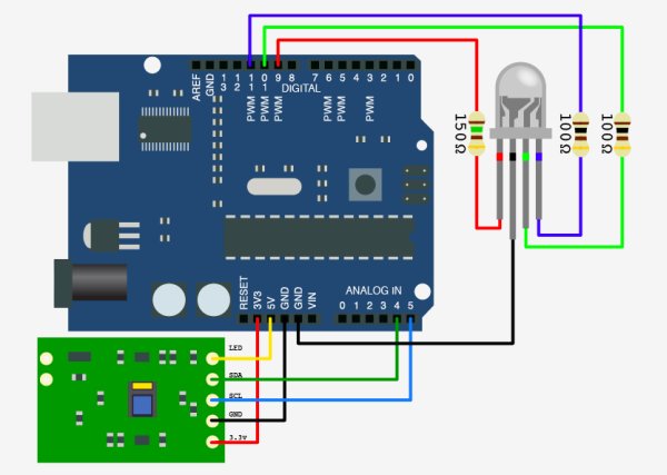
Mostly what you need to know about hooking up an I2C device to your arduino is that I2C is a 2-wire serial connection, SDA (Data) and SCL (clock) – On your arduino (everything but the mega) SDA is on analog input pin 4, and SCL is on analog pin 5. On an arduino mega, SDA is digital 20, and SCL is digital 21.
The ADJD-S371 has 4 sensors on it to detect Red, Green, Blue, and Clear. It reports back an individual reading from each sensor. The white, or clear, sensor is mainly for sensing brightness, but because the LED we will be using to reproduce the color is only an RGB LED, we are just going to disregard the white value.
The ADJD-S371 is designed to sense reflected light using its onboard LED, but I have found that by turning the onboard LED off, it works even better for sensing projected light (like from your monitor or projector). If you are interested in using the sensor for sensing reflected colors, you want the sensor to be about 1-2mm from the subject so the onboard LED can bounce off the material and back to the sensor.
It is not clear in any of the documentation, but I believe from looking at the schematic, and reading forums, that the onboard LED should be powered by 5v, not 3.3v. If this is wrong, please let me know, but the LED is too dim to work when powered at 3.3v.
For more detail: Sensing color with the ADJD-S371 + Arduino