
Summary of Self Balancing Unicycle
This article details the construction of a Self Balancing Unicycle, an edgy project reusing components from previous builds like the self-balancing scooter. The build involves welding a rigid steel frame, integrating a 24VDC motor with a scooter wheel kit, and using an Arduino UNO as the central controller. The electronics setup connects the microcontroller to a Sabertooth motor controller, a 5 DoF analogue IMU for balance sensing, and user interfaces including a deadman switch and trim adjustment toggle.
Parts used in the Self Balancing Unicycle:
- Steel square tubing for frame
- 24VDC 300W motor
- Arduino UNO
- Sabertooth 2x25 Motor Controller
- 5 DoF analogue IMU
- Scooter wheel, sprocket, chain and axle kit
- Batteries
- Shielded multi core cable
- Heavy power cable for motors
- Deadman switch
- Toggle switch for adjusting balance position
- DC connector for Arduino
- DIL pins to suit Arduino
- Double sides tape
- Screws
- Drill and drill bits
- Welding equipment and safety gear
- Soldering iron and solder
- Wire cutter and wire strippers
- Heat shrink and hot air gun
- Second hand unicycle seat
- Steel pipe, nut and star hand knob tightening screw
- Acrylic plate
Following the popularity of our self balancing scooter and the SciChair we decided to try something a little edgier, the Self Balancing Unicycle.
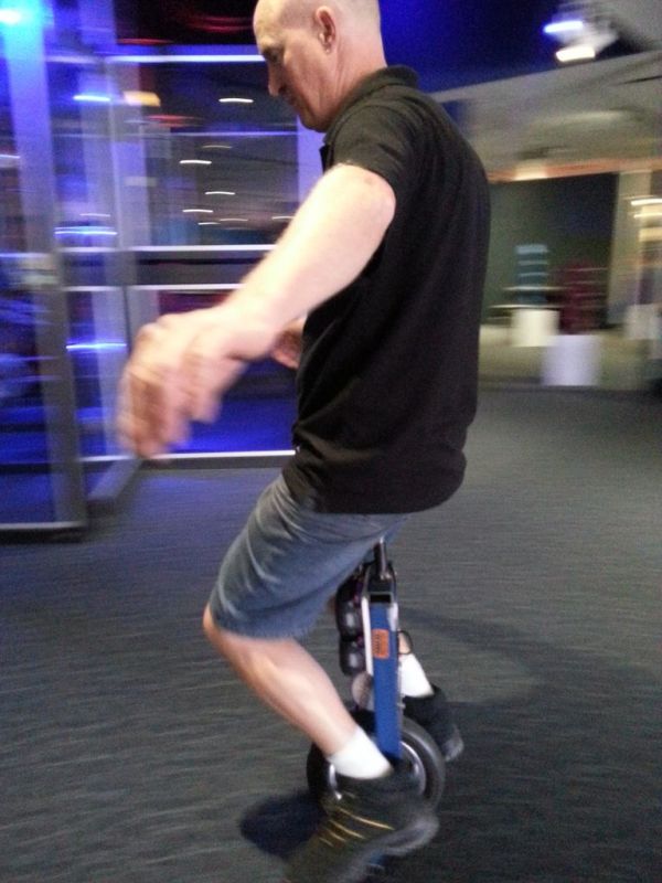
This project reuses a lot of stuff from our previous projects, using an arduino as the brains behind the scenes.
Step 1: Ready your tools
Before we begin lets ensure we have everything we need. For this project you probably want to be fairly comfortable with welding as you need to build a rigid frame.
Additionally you will need:
•Steel square tubing for frame
•24VDC 300W motor
•Arduino UNO – Check your local suppliers or eBay.
•Sabertooth 2×25 Motor Controller ( www.dimensionengineering.com or a local supplier)
•5 DoF analogue IMU – available on ebay (to be replaced with digital IMU at some point)
•Scooter wheel, sprocket, chain and axle – available as a kit
•Batteries
•Shielded multi core cable for the accelerometer and heavy power cable for the motors
•Deadman switch
•Toggle switch for adjusting balance position.
•DC connector for Arduino.
•DIL pins to suit Arduino
•Double sides tape
•Screws etc
•Drill and drill bits
•Welding equipment and saftey gear
•Soldering iron and solder
•Wire cutter and wire strippers
•Heat shrink and hot air gun to shrink it
Step 2: Frame and motor

The seat is sourced from a second hand unicycle as we are lucky enough to work in an office where you can rely on someone having a unicycle they don’t ride much anymore. The shape of the seat is important as you need to be able to shift your centre of gravity forward and backward on the seat, something more difficult on a regular bicycle seat. We attached it to the frame with a simple steel pipe, nut and star hand knob tightening screw.
The wheel, sprocket, chain, and axle all came in a kit designed for a scooter.
We used 25x50mm tubing for the frame and 25mm for the foot pegs. A couple of plates across the middle of the frame served to mount the single motor with a piece of acrylic to which we glued or screwed the electronics.
The axle was set in a channel which allows the two sprockets of the motor and wheel to be moved so the chain can be easily fitted. A bolt above the axle stops it from suddenly sliding upwards when in use.
Step 3: Connect arduino to Switches
Electronics
We built this model with an ardunio nano but are in the process of transitioning to an arduino uno to keep our projects on a standard platform. The code and pin-outs provided here are for an arduino uno.
To connect the Arduino to the 3 position rocker switch to adjust trim and the push button kill switch:
Arduino – Switch
GND -> 3Pos cen, push button -ve
D9 -> Push button +ve
D10 -> 3Pos 1
D11 -> 3pos 3
Step 4: Arduino to ESC
Now to hook the motor speed controller up to the serial interface on the electronic speed controller (ESC).
Arduino ESC
GND -> 0V connect this to the same rail that you were using for the sensor
5V -> 5V
D13 -> S1
This would also be a good time to set the DIP switches on the Sabertooth to the right settings for serial control.
1 – On
2 – Off
3 – On
4 – Off
5 – On
6 – On
Step 5: Arduino to IMU
Next we will connect the Arduino to the IMU (Inertial Measurement Unit). As we’re still waiting on the libraries for the new digital IMUs this project was created using the now harder to obtain analouge IMU, previously sold by sparkfun, now available on ebay (link).
A0 -> Y4.5
A1 -> Z Acc
A2 -> Y-Rate
A3 -> X-Rate
3.3V -> 3.3V
GND-> GND
For more detail: Self Balancing Unicycle
- Why is the second hand unicycle seat important?
The specific shape allows the rider to shift their center of gravity forward and backward, which is more difficult on a regular bicycle seat. - What size tubing was used for the frame and foot pegs?
The builder used 25x50mm tubing for the frame and 25mm tubing for the foot pegs. - How do you adjust the chain tension during assembly?
The axle is set in a channel that allows the two sprockets to be moved so the chain can be easily fitted. - Which Arduino pin connects to the push button kill switch positive terminal?
Digital pin D9 connects to the push button positive terminal. - What are the required DIP switch settings for serial control on the Sabertooth?
Switches 1, 3, 5, and 6 should be On, while switches 2 and 4 should be Off. - Why was an analogue IMU used instead of a digital one?
The project used an analogue IMU because the libraries for the new digital IMUs were not yet available at the time. - Can this project be built without welding skills?
No, the article states you need to be fairly comfortable with welding to build the required rigid frame. - What component prevents the axle from sliding upwards during use?
A bolt placed above the axle stops it from suddenly sliding upwards when in use.
