Project Summary:
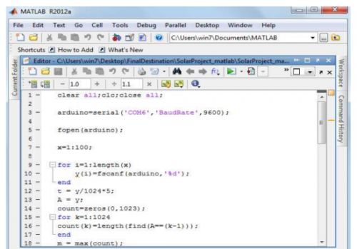
We have designed an Oscilloscope using PC and Arduino Board. The signal is first of all fed to the Arduino Board where the analog signal is converted to a digital signal by the ADC which is then serially outputted to the PC and is read by the MATLAB software via the COM ports. Here the signal is read in the form of digital data but then is converted to analog one by using the resolution of the ADC used by the Arduino Board. The MATLAB software was then used to plot the signals.
Full Project:
The input to be plotted is given to one of the five analog pins in the board. The software used for interfacing the board with the PC is Matlab R2012a. The compiler Arduino 1.0 has been used for uploading the codes to the board. The MAX 232 Line Driver and ATmega328 Processor has been used. The various components used in this designing has been illustrated briefly in the coming sections.
Full project in PDF: DESIGNING A PC OSCILLOSCOPE
Circuit diagram:
Bill of Materials:
Arduino Board
LM358 IC
RESISTORS:
3PCS 1Mohm
CAPACITORS:
2PCS 0.01 µF
For more detail: A PC and an Arduino: here’s your DIY Oscilloscope