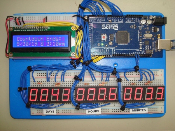
I have been a school teacher for most of my adult life, and like most students, I look forward to the long summer break that awaits us each year. This year as one of my classes learned the basics of LED control with Arduino and then graduated on to displaying simple messages with 4-digit 7-segment display units, I came up with an idea to display a countdown to the end of the school year on the corner of my desk for all to see as they entered the class. I had also been dabbling with the use of ports and 2D arrays in Arduino, so I decided to incorporate both of those elements in the design and coding. The unit shown above is the final product, which you can see also has an LCD screen displaying the end date/time for the countdown, utilizes three 4-digit 7-segment display units connected to an Arduino Mega to utilize all the additional I/O pins and avoid additional circuitry.
Step 1: The 4-Digit 7-Segment Displays
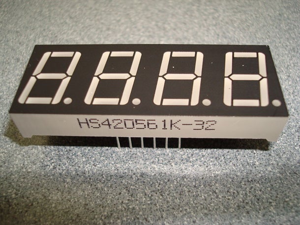
The obvious starting point is to become familiar with the 4-digit 7-segment displays. These units came from some Elegoo stater kits we had purchased for classroom use but could most likely be purchased with the part you you can see on the image above. In addition to the image of the physical device, above you can also can also see the pin-out and the schematic for the unit. Programming an Arduino to individual display characters on these is pretty straight forward, however getting entire words or numbers to display at the same time is where is gets interesting. Like any 7-segment display, numbers and some characters can be displayed by turning on different combinations of of the lettered segments; the twist with a 4-digit 7-segment unit is that all the individual segments from each digit are tied together, which each digit only having it’s own individual common cathode or anode to control seperately. In reality, the only way to make theses units display a word or number is still one digit at a time; however the digits are turned on and off so fast that too the human eye it appears to be on all the time.
Step 2: Understanding (and Using) Arduino Ports
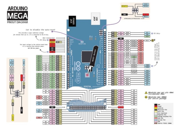
To avoid having to use thousands of “digitalWrite” commands to turn on and off all the combinations I would need, I decided to familiarize myself with the use of ports on the Arduino platform. With this command (ex: PORTA = B01110101;) eight digital I/O pins can be turned on and off simultaneously with a 1 being equivelat to writing a “HIGH” to that pin and a 0 being the same as writing a “LOW” to the pin. Each port corresponds to 8 pins on the Arduino and can be written to in either binary (as I used) or hexadecimal. An easy example to see is ports F and K on the Arduino Mega shown in the pin-out above, with PORTF corresponding to analog pins A0-A7 and PORTK corresponding to analog pins A8-A15. Many thanks to the Adafruit community for their work on THIS spectacular pinout!
Step 3: Laying It All Out
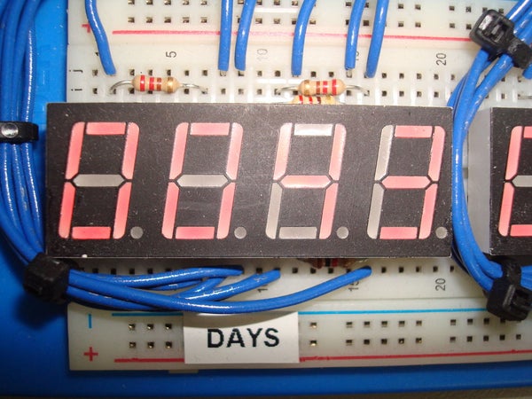
Although hard to see on the images above, I decided the most logical layout for the programming that lay ahead, was to divide each 4-digit 7-segment into upper and lower half’s and then assign each half to a specific port. This would allow me to easily look at the number I needed and then turn on the appropriate segments with a binary output to the port in question. Using the hexadecimal version of the port command would have made each command (actually the 2D array the command is calling) shorter but it seemed easier to see the high/low combinations when laying out the code versus having to convert those same combinations in hex, even if the code would be more compact in the long run. To aid in the process, I created a chart to show what digits/segments were connected to what port assignment. You can also see in the image above that current limiting was accomplish through the common-cathode pin of each digit instead current limiting each individual segment.
Step 4: The Code – CountUpDownTimer
After several failed attempts to run a series of nested for loops to control the timing and the displays, I began looking into parallel processing as it applies to Arduino. Eventually I came across a preexisting library called “CountUpDownTimer” which is available HERE at the Arduino Playgound. This library performs the timing for you in the background allowing you to call hours, minutes and seconds when needed. Those values are then passed as parameters to an array which turns on the proper segments to dispaly the corresponding number. The only complication (besides creating the array – more on that next) was that I had to modify the library to add the “ShowDays” method that was not part of the original code.
#include <CountUpDownTimer.h>
CountUpDownTimer T(DOWN, HIGH); //Create the timer object
void setup(){

//Setting all digital pins as outputs
 for (int i=3; i<=53; i++)
  pinMode(i, OUTPUT);
//Setting all analog pins as outputs
 for (int a=A0; a<=A15; a++)
  pinMode(a, OUTPUT);

T.SetTimer(52,07,17,00); // (days, hours, minutes, seconds)
T.StartTimer();
}
void loop() {

T.Timer();
int stepDelay = 50;
long sm = T.ShowMinutes();
long sh = T.ShowHours();
long sd = T.ShowDays();

   for(int c = 0; c < 4; c++){
      PORTB = upperArray[sm][c];
      PORTL = lowerArray[sm][c];
      PORTA = upperArray[sh][c];
      PORTC = lowerArray[sh][c];
      PORTF = upperArray[sd][c];
      PORTK = lowerArray[sd][c];

      delayMicroseconds(stepDelay);
    }
}   <br>
Step 5: The Code – 2D Array
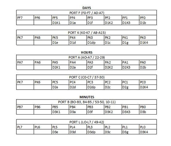
The values to drive the ports were placed in a separate 2D array which is broken into two halves, one for the upper part of the display and one for the lower part. The port assignments are based on the pin-outs of the display with each column representing the corresponding digit. The key here is applying the proper combinations of highs and lows to both the individual segments and the proper common cathode for each successive digit. The 2D array is 270 rows long to account for the entire school year and four columns wide for the four digits in each display. Although the hours and minutes never call a majority of the array, it seemed easier to use the same structure to drive those displays versus a custom array for each section. The first few lines of the upper and lower half arrays are shown below. I also created the chart you see above showing what ports outputs corresponded to what segments to minimize mistakes and maintain my sanity.
byte upperArray[270][4]
  {B00011111,B00111011,B00111101,B00111111},  //00u
  {B00011111,B00111011,B00111101,B00100111},  //01u
  {B00011111,B00111011,B00111101,B00110111},  //02u
  {B00011111,B00111011,B00111101,B00110111},  //03u
  {B00011111,B00111011,B00111101,B00101111},  //04u
  {B00011111,B00111011,B00111101,B00111110},  //05u
  {B00011111,B00111011,B00111101,B00111110},  //06u
  {B00011111,B00111011,B00111101,B00110111},  //07u
  {B00011111,B00111011,B00111101,B00111111},  //08u
  {B00011111,B00111011,B00111101,B00111111},  //09u
  {B00011111,B00111011,B00100101,B00111111},  //10u
byte lowerArray[270][4]{
  {B00110101,B00110101,B00110101,B00110100},  //00
  {B00110101,B00110101,B00110101,B00000100},  //01
  {B00110101,B00110101,B00110101,B00110010},  //02
  {B00110101,B00110101,B00110101,B00010110},  //03
  {B00110101,B00110101,B00110101,B00000110},  //04
  {B00110101,B00110101,B00110101,B00010110},  //05
  {B00110101,B00110101,B00110101,B00110110},  //06
  {B00110101,B00110101,B00110101,B00000100},  //07
  {B00110101,B00110101,B00110101,B00110110},  //08
  {B00110101,B00110101,B00110101,B00010110},  //09
  {B00110101,B00110101,B00000101,B00110100},  //10
Step 6: The LCD Screen – an After Thought
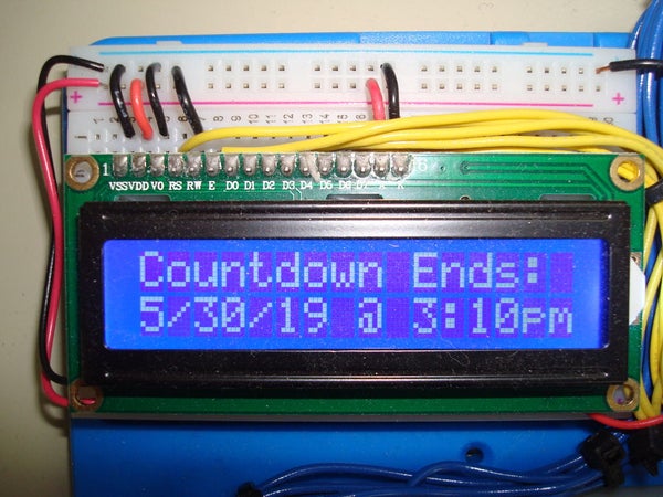
I intially did not intend to include the LCD screen statically displaying the date/time conclusion of the countdown; however, when I purchased the BASE for the project, there was one open space approximately the size of a small breadboard so it seems a logical addition to the project. The display is a standard 16×2 monchrome white-on-blue display which also came from an Elegoo kit. Besides the adtional wiring for the data and control lines, the code modficiations were simple; I added the pre-processor functions including the library and defining the pins that were being used for each required conection, as well as the code to display the static message in the void setup so that would only run once and not effect the timing of the counter. Both modifications are shown below:
#include <LiquidCrystal.h>
const int rs = 17, en = 16, d4 = 21, d5 = 20, d6 = 19, d7 = 18;<br>LiquidCrystal lcd(rs, en, d4, d5, d6, d7);
lcd.begin(16, 2);<br>lcd.setCursor(0, 0);
lcd.print("Countdown Ends:");
lcd.setCursor(0, 1);
lcd.print("5/30/19 @ 3:10pm");
Step 7: Conclusion – Problems and Lessons
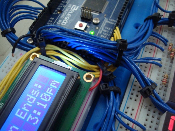
The problematic sections of this project were by far the tedious ones. First, on the hardware side, was making the wiring look neat for the 40+ data lines that were required; next was the creation of the 2D array that holds the high and low combinations necessary to display the proper numbers. One minor hardware modification I had to do was adjusting the size of the current limiting resistors I was using on the fourth digit of each display; due to the timing (and assume the persistence of vision) that digit always appeared a little brighter than the others, so I increase that value until the appearance of all four digits looked uniform. I am sure there is probably a more elegant way to accomplish this with some sort of time sharing or multiplexing, but I learned a great deal from the experience and realized that I have just begun to scratch the surface of what this amazing tool we cal “Arduino” is capable of accomplishing.
Source: School Countdown Calendar