Summary of Schematic of arduino uno
The article explains the Arduino Uno schematic and hardware design, detailing SMD packages, the ATmega328 microcontroller features (memory, I/O, ADC, UART, SPI, TWI), the ATmega16U2 USB-to-UART bridge, power circuitry (5V and 3.3V regulators, MOSFET auto-select, reverse polarity diode, PTC fuse), and protective components used on the Uno PCB to guide integrating Arduino into finished products.
Parts used in the Arduino Uno Schematic Project:
- NCP1117ST50T3G 5V regulator (SOT223)
- LP2985-33DBVR 3.3V regulator (SOT753/SOT23-5)
- M7 diode (SMB)
- LMV358IDGKR dual channel amplifier (MSOP08)
- FDN340P P-channel MOSFET transistor (SOT23)
- ATmega16U2-MU (MLF32)
- ATmega328-PU microcontroller (DIP-28 / TQFP-32 option)
- 16 MHz ceramic resonator (CSTCE16M0V53-R0)
- ICSP header
- USB connector and D+ / D- series resistors
- Varistors for USB lines (Z1 and Z2)
- 100 nF capacitors (decoupling, e.g., C4 and C6)
- Load capacitors for crystals
- Push-button reset switch
- 10 kΩ pull-up resistor on RESET
- PTC fuse MF-MSMF050-2 (USB overcurrent protection)
- Buffers for LED and signals (LMV358 used as buffer)
- Analog reference pin AREF
- Headers: Digital I/O, Analog I/O, Power, and USB power header
This article describes the operation of the Schematic of Arduino Uno from the standpoint of electronic design.
The majority of articles describe Arduino’s software. However, knowing hardware design enables you to move on to the next Arduino level. You can learn how to integrate an Arduino into the design of a finished product, including what to keep and what to omit from your original concept, if you have a solid understanding of the electronic layout of your Arduino hardware.
Overview of Components
The Arduino UNO’s PCB design employs SMD (Surface Mount Device) components. Years ago, when I was working on a team to develop a DIY clone for the Arduino UNO, I got into the SMD industry by diving into Arduino PCB design.
There are different families of packages used by integrated circuits.
Many SMD resistors, capacitors, and LEDs include package numbers that reveal their measurements, like the ones below:

The majority of packages are generic and can be applied to various sections with various functionalities. A transistor or a regulator, for instance, can be found in the SOT-223 package.

The following table includes a list of some of the Arduino UNO’s components along with a description of each package:
| Part | Package |
|---|---|
| NCP1117ST50T3G 5V regulator | SOT223 |
| LP2985-33DBVR 3.3V regulator | SOT753/SOT23-5 |
| M7 diode | SMB |
| LMV358IDGKR dual channel amplifier | MSOP08 |
| FDN340P P-channel MOSFET transistor | SOT23 |
| ATmega16U2-MU | MLF32 |
Review of the Arduino UNO System
We must first have a broad understanding of the system before we can comprehend the hardware of the UNO.
In the following compilation using the Arduino IDE, your code needs to be transferred via USB to the Arduino UNO’s primary microcontroller. You need a bridge to translate signals between the host USB signals and the main microcontroller’s serial interface (UART interface) because the primary microcontroller lacks a USB transceiver.
The ATmega16U2 bridge in the most recent revision has both a USB transceiver and a serial interface (UART interface).
Use the USB as a power source to run your Arduino board. Using a DC jack is another choice. Which power source will be used if I attach both a DC adapter and a USB? you might wonder. The “Power Part” section of this article will cover the solution.
You should press the board’s push button to reset it. Every time the serial monitor from the Arduino IDE is opened should serve as a further source of reset.
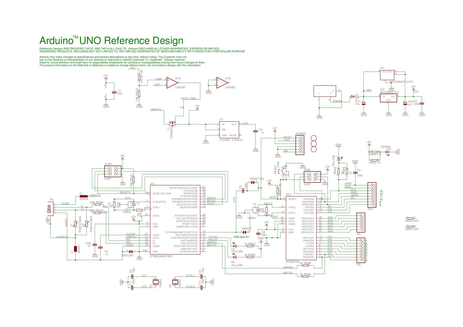
The original Arduino UNO schematic has been redistributed below for easier reading. While you are reading this post, I suggest that you download it and use Eagle CAD to access the PCB and schematic.
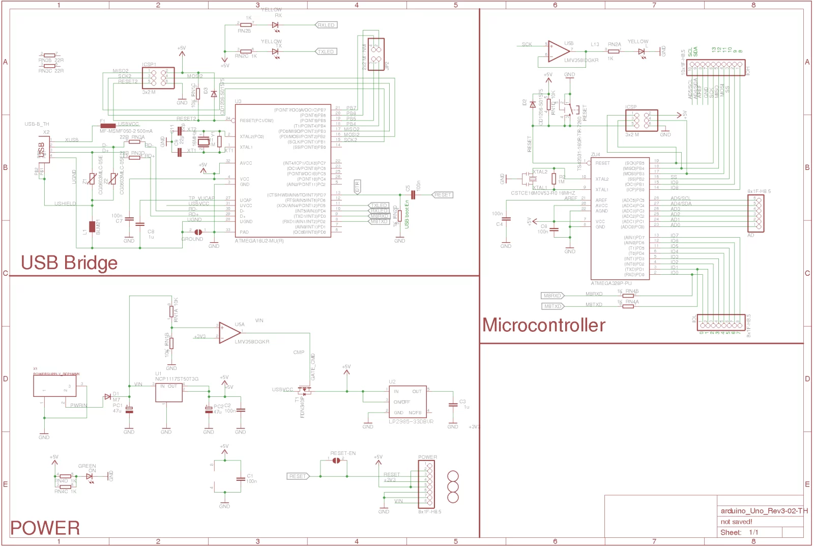
The Microcontroller
It’s crucial to realize that the Arduino board has a microprocessor and that it is this microcontroller that carries out the instructions in your program. The usual nonsense statement “Arduino is a microcontroller” will never be used again if you are aware of this.
The main controller of the Arduino UNO R3 is an ATmega328 microprocessor. The ATmega328 is an MCU from the AVR family. As an 8-bit device, it has internal registers and a data-bus architecture that are built to support 8 parallel data streams.
Three different kinds of memory are available in the ATmega328:
- Flash memory: Non-volatile memory of 32 KB. The reason you don’t have to upload your program every time you unplug your Arduino from its power source is that this is used for application storage.
- SRAM memory: Volatile memory of 2 KB. This is used to store variables that the running application needs.
- EEPROM memory: Nonvolatile memory of 1 KB. This can be used to save information that must be accessible even after the board is turned off and back on.
Let’s quickly review some of this MCU’s specifications:
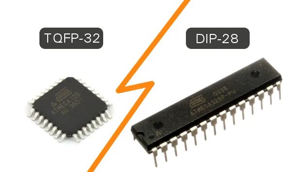
Packages:
This MCU contains 28 pins in a dual in-line package because it is a DIP-28 device. Power and I/O pins are among these pins. The majority of the pins are multipurpose, which means that depending on how you set them up in the software, the same pin can be used in various modes. Because the microcontroller does not need a distinct pin for each function, the number of pins is reduced. Due to the fact that a single I/O connection can support several functionalities, it can also increase the flexibility of your design.
There are further ATmega328 packaging options, such as the TQFP-32 SMD package (Surface Mount Device).
Power:
The supply voltage range for the MCU is 1.8 to 5.5 V. There are limitations on the working frequency, though. For instance, a supply voltage of at least 4.5 V is required if you want to use the highest clock frequency (20 MHz).
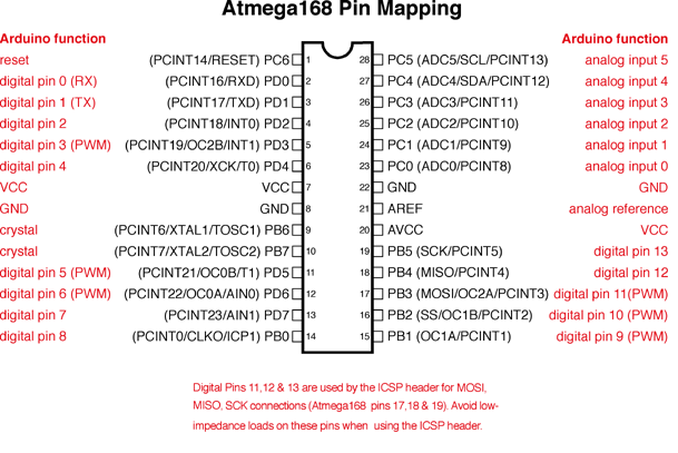
Digital I/O:
The three ports on this MCU are PORTC, PORTB, and PORTD. These ports’ whole pinout is available for general-purpose digital I/O as well as the alternative uses listed in the pinout below. As an illustration, ADC inputs can be used in place of digital I/O on PORTC pins 0 to 5.
Additionally, several pins can be set up as PWM outputs. The Arduino board has the symbol “for these pins.
Note: The ATmega168 and ATmega328 are pin compatible and nearly identical. In contrast to the ATmega168, which has 16KB flash, 512 bytes EEPROM, and 1KB RAM, the ATmega328 has 32KB flash, 1KB EEPROM, and 2KB RAM.
ADC Inputs:
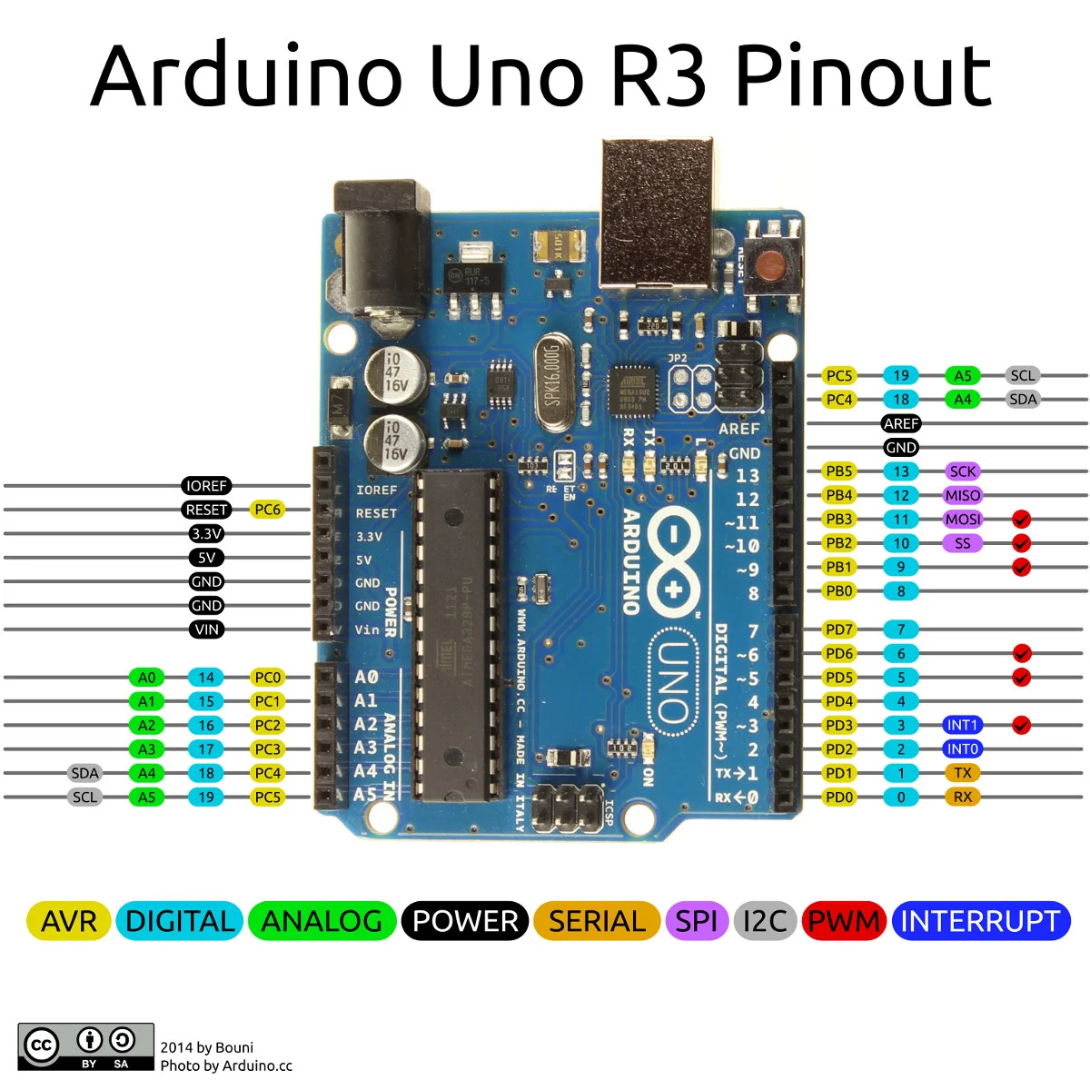
This MCU features six channels, PORTC0 to PORTC5, each with an A/D converter with a 10-bit resolution. The analog header on the Arduino board is connected to these pins.
One typical error is to assume that because the header on the board says “Analog,” the analog input is solely intended to be used for A/D functions. You can actually utilize them as digital I/O or A/D.
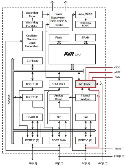
The pins connected to the A/D unit are as follows, as indicated in the picture above (via the red traces):
- AVCC: The A/D unit’s power pin.
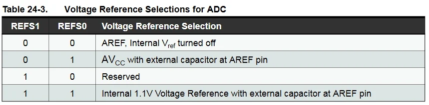
- AREF: The input pin is utilized if you wish to use an external voltage reference instead of the internal Vref for the ADC. Utilizing an internal register, you can adjust that.
UART Peripheral:
A serial interface is a universal asynchronous receiver/transmitter (UART). There is only one UART module in the ATmega328.
The USB-to-UART converter circuit as well as pins 0 and 1 in the digital header are both linked to the UART’s RX and TX pins. If you’re already utilizing the UART to send and receive data through a USB, you must stop using it.
SPI Peripheral:
Another serial interface is the SPI (Serial Peripheral Interface). There is only one SPI module in the ATmega328.
It can be used as both a serial interface and a standalone programmer to program the MCU. The header next to the MCU on the Arduino UNO board or the digital header both provide access to the SPI pins as seen below:
11<->MOSI
12<->MISO
13<->SCK
TWI:
Only two wires, serial data, and a serial clock make up the I2C or Two Wire Interface: SDA, and SCL.
From the final two pins of the digital header or pins 4 and 5 of the analog header, you can access these pins.
Other Functionality:
The MCU also has other features including the timer/counter modules’ operation. The functions that you don’t use in your code could not be known to you. For further details, please see the datasheet.
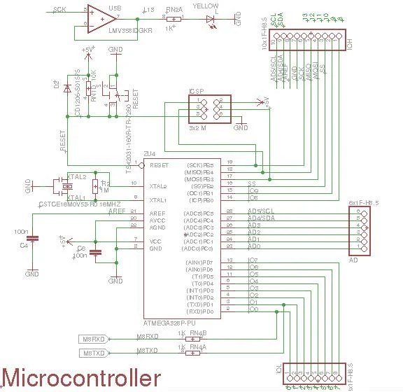
The microcontroller component of the electronic design includes the following:
- ATmega328-PU: The MCU we just discussed.
- IOL and IOH (Digital) Headers: In addition to GND, AREF, SDA, and SCL, these headers also serve as the digital header for pins 0 to 13. Keep in mind that pins 0 and 1 are used to link the USB bridge’s RX and TX.
- AD Header: The header for analog pins.
- 16 MHz Ceramic Resonator (CSTCE16M0V53-R0): connected to the MCU’s XTAL2 and XTAL1 ports.
- Reset Pin: This pin has an internal pull-up resistor, but the AVR Hardware Design Considerations application note (AVR042) states that “if the environment is noisy, it can be insufficient and reset may occur sporadically.” It is pulled up with a 10K resistor to help prevent spurious resets in noisy environments. If the user clicks the reset button or if the USB bridge issues a reset, the device is reset. Additionally visible is the D2 diode. In the same app note, it is advised to add an ESD safety diode from RESET to Vcc if high voltage programming is not being used because it is not internally provided.
- C4 and C6 100nF Capacitors: To reduce supply noise, these are included. A capacitor’s reactance diminishes with frequency:
Xc = 12πfC
The capacitors provide a low-impedance channel to the ground for high-frequency noise signals. The most typical value is 100nF. The AAC textbook contains more information on capacitors. - PIN13: This has an LED attached to it as well as a connection to the MCU’s SCK pin. To operate the LED, the Arduino board makes use of a buffer (the LMV358).
- ICSP (In-Circuit Serial Programming) Header: Using an external programmer, this is how the ATmega328 is programmed. The In-System Programming (ISP) interface is related to it (which uses the SPI pins). This kind of programming is typically unnecessary because the bootloader manages the MCU’s programming from the UART interface, which is connected via a bridge to the USB. When the MCU must be flashed for the first time in production, for instance, using a bootloader, this header is used.
The USB-to-UART Bridge
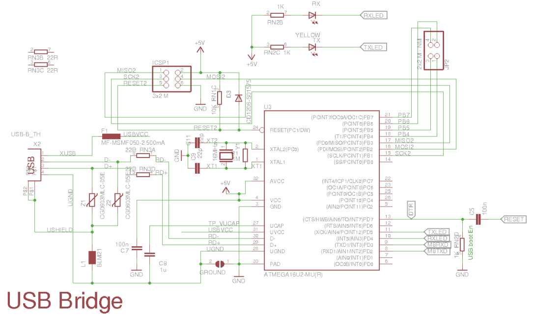
The USB-to-UART bridge part’s function is to convert USB interface signals to the UART interface, which the ATmega328 understands, utilizing an ATmega16U2 with an inbuilt USB transceiver, as was covered in the “Arduino UNO System Overview” section. The ATmega16U2 is updated with specialized firmware to accomplish this.
This section and the microcontroller section are comparable from the standpoint of electronic design. This MCU is equipped with an ICSP header, a Vcc filter capacitor, and an external crystal with load capacitors (CL).
The D+ and D- USB lines include series resistors, as you can see. These provide the USB signals with the correct termination impedance. For more information on these resistors, see the following:
- Reasons for USB data series resistors
- FAQ for USB developers
Voltage-dependent resistors (VDRs), commonly known as varistors, are Z1 and Z2. They serve to guard against ESD transients on the USB lines.
The Atmega16U2 is able to send a reset pulse to the Atmega328 by series-connecting a 100nF capacitor to the reset line.
The Power
You have the choice of using a DC jack or a USB as a power source. It’s time to respond to the following query: “Which will provide power if I connect a USB and a DC adapter at the same time?”
The M7 diode, an SMD version of the well-known 1N4007 diode, is linked to the Vin of the 5V regulator, the NCP1117ST50T3G, through the DC jack input (PDF). This diode offers protection against reverse polarity.
The 3.3V regulator, LP2985-33DBVRinput,’s is connected to the output of the 5V regulator as well as to the remaining 5V net in the circuit. 5V is immediately accessible from the power header 5V pin.
Another 5V source is USB VCC, which has its source connected to the 5V net and its drain connected to the drain of a P-channel MOSFET called the FDN340P. The LMV358 op-amp being utilized as a comparator has its output connected to the transistor’s gate. The two are compared: 3V3 and Vin/2. The P-channel MOSFET will be off and the comparator output will be high when Vin/2 is greater. If no Vin is applied, the comparator’s V+ is dragged down to GND and its Vout is low, turning on the transistor and connecting the USB VCC to 5V.

The 3V3 regulator is the LP2985-33DBVR. The LDO (Low Dropout) characteristics of the 3V3 and 5V regulators allow them to maintain voltage regulation even when the input and output voltages are in close proximity. Compared to earlier linear regulators like the 7805, this is an improvement.
I’ll talk about the powerful protection that Arduino UNO offers as my final topic.
As previously noted, a series M7 diode is used in the input to safeguard VIN against reverse polarity when it comes via a DC connector. Be mindful that the power header’s VIN pin is not shielded. This is due to the fact that it is wired after the M7 diode. In my opinion, they could have connected it before the diode to offer the same protection, so I’m not sure why they chose to do that.

A PTC (positive temperature coefficient) fuse (MF-MSMF050-2) is connected in series with the USB VCC when using the USB as a power supply and protects your USB port. This offers 500mA of overcurrent protection. The PTC resistance significantly increases when an overcurrent limit is approached. Following the removal of the overcurrent, resistance falls.
Arduino UNO Reference Design
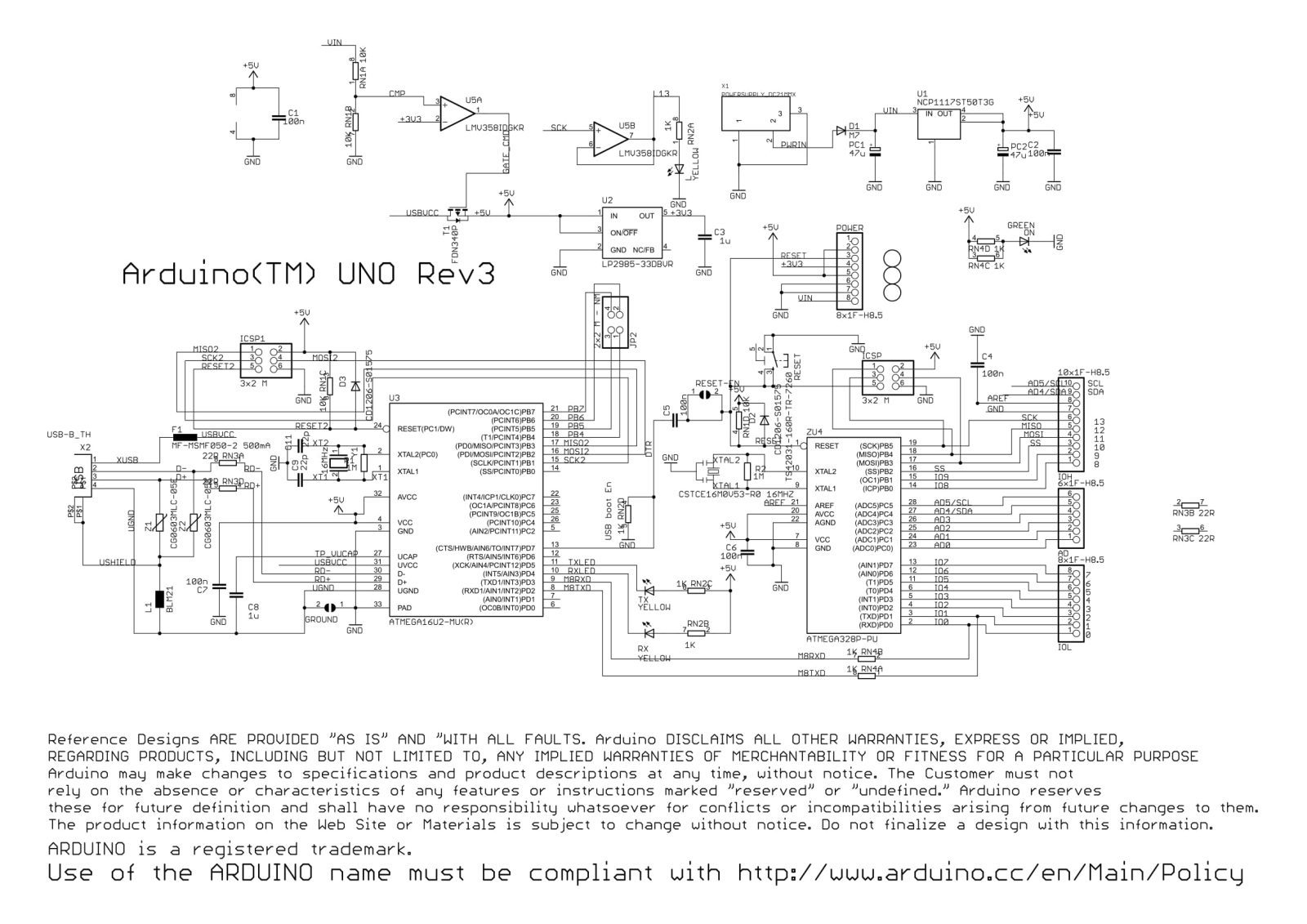
Arduino(TM) Uno Rev3
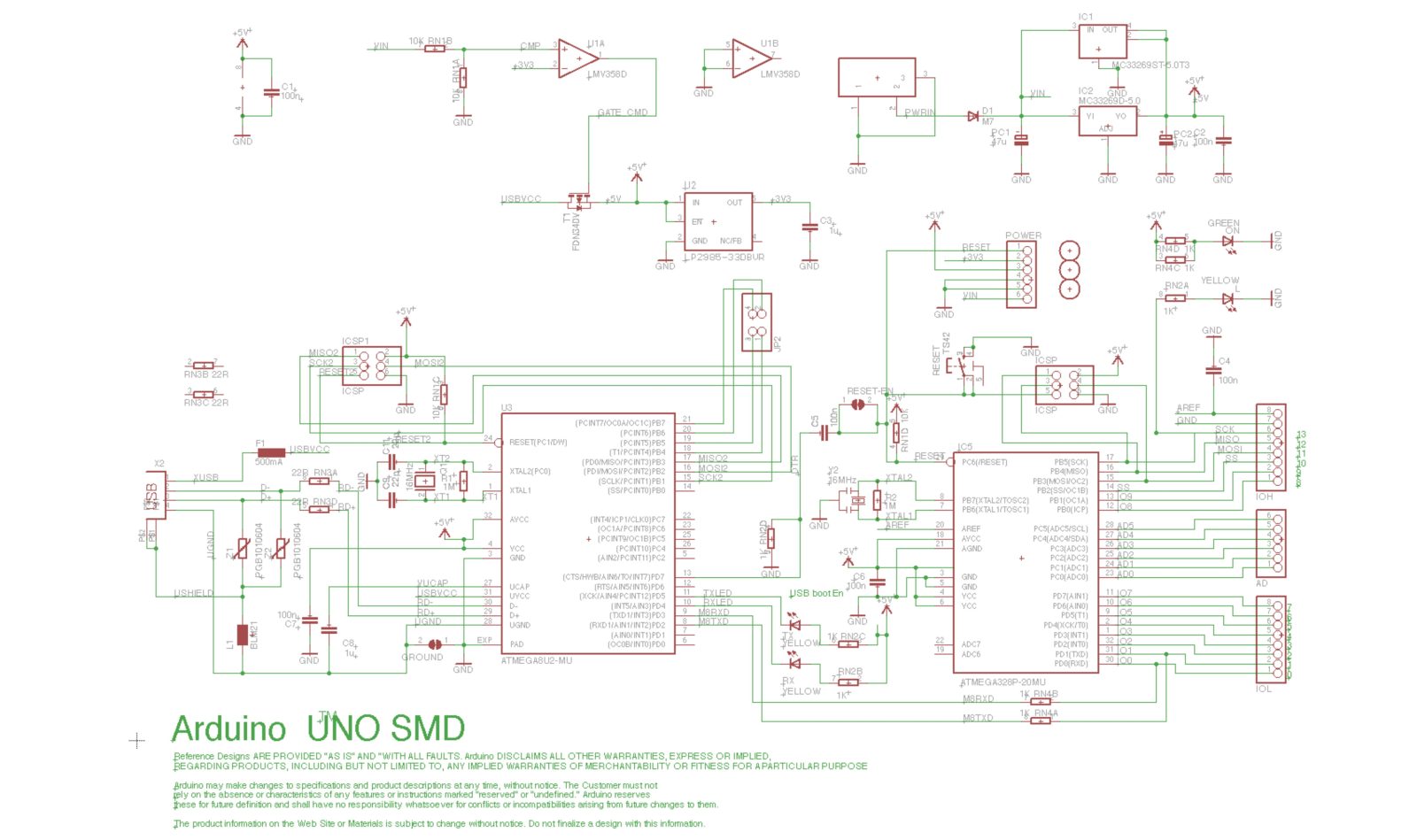
Arduino uno SMD schematic
- What is the main microcontroller used on the Arduino UNO R3?
The ATmega328-PU is the main microcontroller used on the Arduino UNO R3. - How is USB converted to serial for uploading code?
The ATmega16U2 is used as a USB-to-UART bridge with specialized firmware to convert USB signals to the MCU UART. - What protects the USB port from overcurrent?
A PTC fuse (MF-MSMF050-2) in series with USB VCC provides 500mA overcurrent protection. - How does the board select between USB and external DC power?
A P-channel MOSFET (FDN340P) controlled by an LMV358 comparator switches USB VCC to the 5V net depending on Vin/2 compared to 3.3V. - Which regulators provide 5V and 3.3V on the board?
The 5V regulator is NCP1117ST50T3G and the 3.3V regulator is LP2985-33DBVR. - What component protects against reverse polarity on VIN?
An M7 diode is placed in series with VIN to protect against reverse polarity from the DC jack. - How many ADC channels does the ATmega328 provide?
The ATmega328 provides six ADC channels, PORTC0 to PORTC5, each with 10-bit resolution. - Can the analog pins be used as digital I/O?
Yes, the analog header pins can be used either as ADC inputs or as digital I/O. - What is the purpose of the ICSP header near the MCU?
The ICSP header provides access for in-circuit serial programming using the SPI pins to program the ATmega328 with an external programmer. - Why are 100 nF capacitors used on the board?
100 nF decoupling capacitors reduce supply noise by providing a low-impedance path to ground for high-frequency noise.