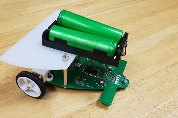
I made this project in collaboration with Ruben Says, for our studies in electromechanics at the HoGent. The assignment was to make a line follower robot, which is a little cart that by using its sensors is able to follow a black line on a white paper.
In this tutorial I will give you an inside look in how to make this robot, so you can understand how this robot is working and you should be able, by following the steps, to make it yourself. All the files that I made and used for this project are of course available for free.
Hopefully you will find this interesting, let’s begin!
Step 1: Choose the Key Components
The Specifications:
The objective is to create a small, ‘cheap’ (=max. 50 euros), lightweight, line follower robot. It must include a light sensor array with a PID controller, which can be tuned via a wireless connection. It should reach a speed of >0,5 m/s and should be able to continuously follow a printed track (printed black lines on a white paper). Those printed tracks are 1,5 cm wide, have a minimal radius of curvature of 10cm and can contain crossroads, in which case the robot should go straight forward. You can find the files of the tracks below. Other constraints are the height and width of the robot that shouldn’t be more than 12cm and we should use as much smd components as possible, rather than using through-hole components.
In summary: the Hardware should consist out of:
- Energy source
- DC-Motor’s
- H-bridge
- 6 Analog Light sensors
- PID-Control
- Wireless Communication
- Start/stop button
Choosing Key Components:
With these specs in mind we started our brainstorm session and made the first big decisions: We decided to use 6V DC motors and a 50:1 gear. We chose the 6V mainly because we wanted to use two 18650 batteries in series as a power source. Because those batteries are a relatively light, easily available, powerful and cheap option for this project. The batteries provide a voltage between 7.4 and 8.4 volts. Taking losses into account this means that it won’t overload a 6V motor while delivering enough amps.
Using the ATmega32u4 microcontroller as the brains for the robot (the chip used for the Arduino Leonardo board) was an obvious choice, as it should be able to compute all the calculations needed for this project. This chip will be connected with some in- and outputs:
The chip should get two inputs: a light sensor array and a 5 volts. For the light sensor array we went with the QRE1113 sensors, as their specs fit our specs and are commonly found in likewise projects. We will be using six of those. The five volts will be delivered through a voltage DC to DC regulator reg1117, because it is an easy to find smd component and fits our description.
The chip has one major output: the H-Bridge. We opted for the DRV8833, as this was the first smd H-bridge we came across that met our specifications. Probably there are way more good alternatives out there, but why look further if you got what you need?
The chip has two communication lines (In/Out), one through usb and one via bluetooth. For usb we went with a mini USB port mainly because it solders on more easily than a micro USB port. For the bluetooth we chose the HC-05module, as I had one laying around anyway, these modules are easy to come by and work perfect for this application.
Step 2: Design Electrical Circuit
For this project we wanted to design our own circuit board, which was a thing to keep in mind when designing our electrical circuit. We ended up using the ‘Eagle’ software to create our circuit, because it is relatively easy to work with, freely available and it allows the creation of pcb design that can later be printed.(https://www.autodesk.com/products/eagle/free-down…)
Another advantage of this software is that is has already quite a big component library and when they don’t have the component needed somebody else probably already did create it, which then is easily imported into the software. For example on SnapEDA as shown below:
Regarding the creation of the pcb, it was important that when inserting a component, we picked a component with a good footprint. This made the initial process of creating the electrical circuit a little harder, but paid off big time in the next step. To make a good decision, there are a few things you have to keep in mind. Starting with the main take-away: We wanted it to be as small as possible, so the robot would be as small and compact as possible. However, we are not always able take the smallest component; there are a few limitations:
- We want to use smd components so we can make an optimal use of both sides of the pcb. So watch out not to use the through-hole footprints.
- Does the component you want to use exist, and is it easily available? This is a question you should answer for every new component you add, just run it through google and/or a sellers website and check if the specifications match your needs in the datasheet. Don’t forget that smaller components often have lower rated voltages, so make sure that checks out as well.
- It also happens that a slightly smaller component exponentially rises in price, then you have to take into consideration if that rise in price is worth the minimal win in size.
- Keep in mind we are not robots and we have to solder it by hand. So even though it is possible I really wouldn’t suggest using components smaller than the 1206 footprint.
- More on this topic I found on this website: https://www.electronics-notes.com/articles/electr…
In hindsight we should have used a bigger footprint and component for the crystal, because even though it worked, we had a hard time soldering it onto the board and we managed to destroy one.
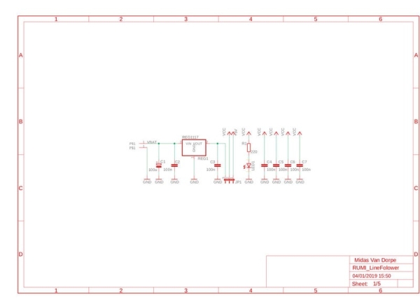
As you can see I divided the circuitry into five schematics, where I will briefly shed some light on.
1. The first schematic is built around the voltage regulator for the ATmega32u4 (REG1117). The atmega likes to receive a nice 5 dc voltage, to achieve that the voltage regulator transforms the unstable input to a relatively stable 5 volts. To increase that stability we use ‘snubbers’, which are the 100nF capacitors (to remove spike voltages and electromagnetic interference) and a smoothing capacitor, the 100μF capacitor, (to keep the battery voltage as stable as possible). We also wanted to be able to power the board without batteries when connected to the pc, therefore we implemented a jumper to switch between the two sources. Finally there is a status led, to tell us when our circuit gets power, this led has of course a ballast resistor.
2. The second schematic handles the brain of the robot, which need more components than just the ATmega32u4 IC. For starters it needs a clock signal in the form of a timing crystal, this crystal should create a frequency of 16MHz for the ATmega to work properly. In addition to the crystal there are also two 22pF load capacitors and a 1M ohm resistor needed. The crystal is a quartz and is therefore a piezoelectric material. This means that when a certain voltage is applied, it resonates at a particular frequency. For it to work like a metronome properly, every cycle should have a phase shift of 360°, because we want the signal not to interfere with itself. To accomplish this there is an RC circuit (1M ohm and 22pF) which gives you a certain shift and the two load capacitors in series from the crystal point of view which finalise the shift. The lower the combined capacity of the load capacitors is, the higher the produced frequency of the Crystal. The higher the combined capacity, the lower the produced frequency.
We also wanted to add a usb port for data communication. This is just a straightforward connection D+ to D+ and D- to D-, but there have to be some termination resistors in between so the total impedance of the connection matches the usb specifications. SW2 is the reset switch of the ATmega. SW1 is a programmable switch, which will later be programmed as the start/stop switch. LED2 is a programmable light that in the end doesn’t really has an important function, but will be very helpful in verifying that everything works.
One very important thing you can’t forget is to give all the ISCP pins a terminal, so you can connect them later to upload the bootloader. Those pins are the SCK, MOSI, MISO, VCC, RST and GND pin.
3. As it would be kind of unhandy when every time we want to change a setting we have to plug it into a computer, we wanted to implement some bluetooth functionality. We chose the HC-05 module.(Datasheet:http://www.electronicaestudio.com/docs/istd016A.pd…)
This bluetooth module is powered with 3.3V, so we needed another voltage regulator, and again used a REG1117, yet this time a model that gives a steady 3.3V output. Just like before we added a status light, some snubbers and a smoothing capacitor, to create a clean output voltage.
For the date transfer we need to connect the TX to RXD and RX via a voltage divider tot TXD. The voltage divider needs to transform de 5v data line from the Arduino to a 3.3V data input from the HC-05 (This is not needed in the opposite direction because the Arduino can read a 3.3V incoming signal. Finely there are three more components: a switch and two more status lights:
- PIO8 is used to control LED indicating the status. It will blink after power is on.
- PIO9 is used to control LED indicating paring. It will be steady on when paring is successful
- PIO11 is used to set this two mode: AT command mode (if the pin is connect to 3.3V) or Automatic binding transparent data mode (if the pin is connect to GND). The AT command mode is used to configure some characteristics of the device (for example the Master, Slave or Loopback modes). (https://os.mbed.com/users/edodm85/notebook/HC-05-b…)
4. The Sensor Array is quite straight forward as the QRE sensors are not much more than a led with a current-limiting resistor and a phototransistor that is connected to a pull-up resistor (47k) to form a voltage divider that produces an analogue voltage output between 0 V and 5V.
5. At last we have the H-bridge, which is an electronic circuit (IC) that switches the motors on, off, forward or backwards. For the H-bridge I just followed the recommended circuit found in the datasheet (http://www.ti.com/lit/ds/symlink/drv8833.pdf), this example adds some smoothing capacitors for the incoming voltage, some resistors for disabling the sleep function and enabling the outputs. The inputs are connected to Pin 5, 6, 9 and 10 of the Arduino, which are all pwm pins, what is crucial if you want to adjust the speed.
Finally it is a good idea to check your schematics with an ERC check, this won’t verify if your circuit works, but it will verify if everything is connected properly. If this is all finished we can move to the next step: Turning this into a printable pcb.
Step 3: Design the Pcb
Now that we have our circuit we can start the most demanding part of the build, creating the pcb. To start this click in eagle on “switch to board” and you’ll get an empty board with all the components, used in your schematics, next to it connected with tiny lines showing where to make the connections. This was my first attempt on creating a pcb, but as it is not the objective for this Instructable to guide you through designing a pcb, I’ll just point out a few things that are challenging and you can’t forget when designing these. If you just want to get building you can just skip this step.
For me the best approach at this was to first place al the big and main components on both sides of the board. There are immediately some components I was able to give a place by thinking logically: I definitely wanted the leds, the motors, the switches and the jumper on top of the pcb. The sensor array on the other hand obviously had to be on the bottom. The ATmega and the HC-05 I liked to have somewhere in the center and the H-bridge on a somewhat equal distance from the ATmega and the two motors.
Then there are a few things you have to take into a count:
The Smoothing capacitors have to be as close as possible to the voltage regulators.
The Snubbers have to be as close as possible to every vcc input of the ATmega (Thats why there are so many).
The crystal and its components should also be as close as possible tot the ATmega.
Plaats de usb connector en bijhorende weerstanden zo dicht mogelijk tegen de microcontroller.
Some other guidelines that will help you making a working pcb is the following:
Draw in mil’s not in mm.
Grid: 25 mil
Width tracks: min 12 mil for logic tracks, power tracks must be thicker.
Short and thick tracks are always beter then long and thin ones.
Making via’s is beter then long tracks around the pcb.
Make the circuit so compact as possible.
Drilling with 0,6 or 0,7 mm holes.
To create a ground surface:
Draw a polygon around the pcb.
Name it GND.
Then press Ratsnest.
Don’t forget to do a DRC check, to check if everything is connected.
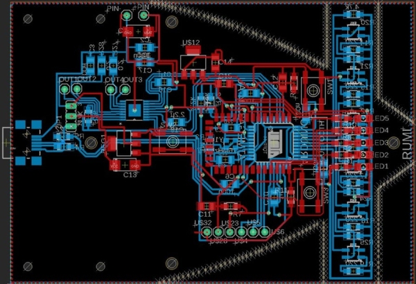
Following all these rules and after hours of intensive work I was able to get the result you can see here.
Finally there was one more esthetical decision to make: “a front spoiler!” To make this happen I drew two circles with there center point equally far away from the center of the pcb. Then I started drawing holes along the lines of those circles. At the point where the sensors are situated I continued to draw the holes around those sensors, thus creating a spoiler. This is one of the details that makes RUMI so unique.
Source: RUMI the LineFollowingRobot