Summary of Rotary Encoder & Arduino
This article explains how to use a rotary encoder (RT) as a digital alternative to analog potentiometers for infinite rotation sensing. It details the RT's internal mechanics, including phase outputs and step detection, and describes connecting it to an Arduino Uno R3 using external interrupts on pins 2 and 3. The text also emphasizes the necessity of hardware debouncing via RC filters to prevent signal errors caused by mechanical contact imprecision.
Parts used in the Rotary Encoder & Arduino Project:
- Rotary Encoder (RT)
- ALPS manufactured component
- Arduino Uno R3
- RC filter (for debouncing)
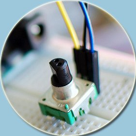
I am not sure, but it was in year 1999, a non-stop (360 degree rotation) potentiometer found in a stereo music system confused me a lot. At that time, I failed to keyed out the strange potentiometer manufactured by ALPS. Later, I learned that it’s a Rotary Encoder (thanks to internet), and bought one such component from an online store for $2. A rotary encoder (RT) is a device that you can rotate infinitely. On most rotary encoders, when you rotate them you will feel a bump (known as steps), and most RTs have about 12 of these per rotation (some have 24 or more). Basically this step is the minimum amount you can rotate the encoder to register any change.
 In principle, with a RT we have two square wave outputs. The figure shown above describes how the phases (A and B) relate to each other when the encoder is turned clockwise (→) or counter clockwise (←). By monitoring the outputs with a microcontroller it is possible to determine the direction← of turn and how far it has turned. Besides, we can count the frequency of the pulses to determine how fast it is being turned.
Literally, RT is a wonderful digital alternative to the old analog potentiometers. Rotary encoders are useful as rotation sensors (or selectors) and look similar to potentiometers, but rotate all the way around continuously, and are divided up into many segments. Each segment has a clicky feeling to it and each clockwise or counter-clockwise movement causes the two built-in switches to open and close. Most RTs also has built in ‘push-on’ momentary switch, usually one side has 3-pins (two coding pins and one common/ground pin) and the other side has 2-pins (N/O switch contacts) for the push-on switch.
As stated, the rotary encoder has 2 coding pins that are either HIGH (1) or LOW (0). If you treat the pins as binary, you can read them as 00, 01, 10, or 11 (sequence the encoder outputs while spinning clockwise is 00, 01, 11, 10). If you have a reading of 01, the next reading can either be 00 or 11 depending on the direction the knob is turned.
Now that your rotary encoder hardware is up and running it’s time to tell your Arduino what to do with the encoder signals. There are the two basic ways to read a microcontroller’s digital input. With polling you read the input all the time inside a loop. With interrupts the microcontroller does any other job, and when a signal arrives from the encoder the controller stops it’s job, jumps to the interrupt routine and then returns to the previous job. This way the microcontroller is concerned with the encoder signal only when a new pulse comes. Since the interrupt signal comes from outside the Arduino it is called as external interrupt. Arduino Uno R3 has two external interrupts: int.0 (pin 2) and int.1 (pin 3). Have a look at the Arduino Reference for more details (http://arduino.cc/en/Reference/AttachInterrupt).
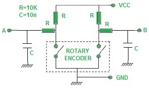 While connecting a RT to Arduino, it is better to add a suitable ‘debouncer’ with the setup to avoid possible encoding errors. This is necessary because inside the rotary encoder two pieces of metal contacts touching each other in an imprecise way as in the case of a mechanical switch, and this will manifest itself as missed steps or even steps back when going forward. Although you can also do this in software, I prefer the hardware way by using an RC filter as shown below.
I will not go into greater detail of the code behind the rotary encoder + Arduino experiment, as featured articles and great tutorials are available all over the web. If you would like to learn more regarding RTs and their usage you might want to read these great works:
For more detail: Rotary Encoder & Arduino
- What is a rotary encoder?
A device that rotates infinitely with steps, serving as a digital alternative to analog potentiometers. - How many steps do most rotary encoders have per rotation?
Most have about 12 steps per rotation, though some have 24 or more. - Can you determine the direction of turn with a rotary encoder?
Yes, monitoring the two square wave outputs allows determination of clockwise or counter-clockwise direction. - Which Arduino pins support external interrupts?
Arduino Uno R3 has two external interrupts located at int.0 (pin 2) and int.1 (pin 3). - Why is a debouncer necessary when connecting a rotary encoder?
It prevents encoding errors like missed steps or steps back caused by imprecise metal contact touching. - What is the preferred method for debouncing mentioned in the article?
The author prefers the hardware way using an RC filter rather than software debouncing. - Does a rotary encoder include a push-on switch?
Most rotary encoders have a built-in momentary push-on switch with two additional pins for N/O contacts. - How does polling differ from interrupts for reading signals?
Polling reads input constantly in a loop, while interrupts allow the controller to perform other jobs until a signal arrives.