This is officially my first Instructables article, so I’m going to admit that I am using this opportunity right now to try it out. Get a feel of how the platform works, the whole user experience side of it. But while I am doing that, I figured I can also use the opportunity to share about a simple project that I have been working on today (using the products from XinaBox, which by the way, is pronounced as “X-in-a-Box”).
In this simple 5-step instructable, I will cover the following topics:
- Components needed
- Connecting the different xChips together.
- Setting up the Arduino IDE environment.
- Writing the code
- And finally, testing the idea out
What I will not be sharing in this instructable:
- As much as I love to dive into explaining what each of those xChips can do and how you can manipulate them to perform certain functionalities, that would not be the goal of this instructable. I plan on publishing other Instructables in the near future that will dive into each of the different xChips that are available through XinaBox’s product catalogue.
- I will not be going into the basics of the Arduino code as I assume that you already have some level of experience with using the Arduino IDE as well as a basic level understanding of C/C++ programming.
Step 1: What You Need…
Technically, most basic product tutorials usually begin with a “Hello World!” example, or even a “Blink” example, which you might already be very familiar with since you have worked with Arduino or Raspberry Pi at some point. But I don’t want to start with that because everyone is already doing the same thing, which makes it a bit boring really.
Instead, I wanted to start with a practical project idea. Something that is both simple enough and scalable into a more complex project idea if you want.
Here are the items that we are going to need (refer to the photos provided for this section of the Instructable):
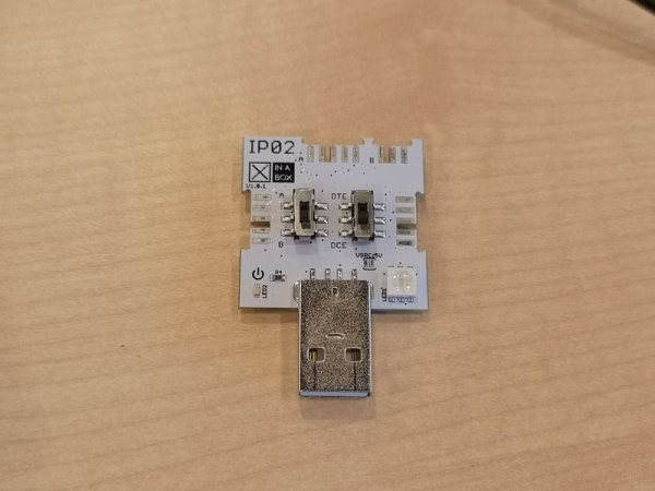
- IP02 – Advanced USB Programming Interface
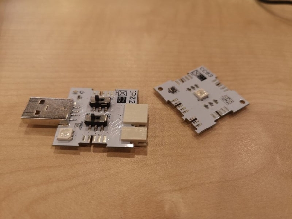
- CC03 – Arm Cortex M0+ Core
- SW02 – VOC and Weather Sensor (which uses the BME680 sensor by BOSCH)
- xBUS connectors – to enable I2C communications between the different xChips (x2)
- xPDI connector – to enable programming and debugging (x1)
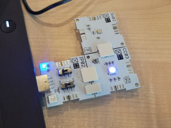
Step 2: Connecting the Pieces
To connect all the pieces together, we will first start with 1 piece of the xBUS connector and xPDI connector.
Following the images that I have provided, notice the orientation of the xChips and where the connectors will go.
Between the IP02 & the CC03 xChips, it’s quite easy to identify the connecting points.
For CC03, it will be the south side. For IP02, it will be the north side of the xChip.
Once that is done, we will add another xBUS connector to the west side of the CC03 xChip.
Done?
Now, just connect the SW02 xChip to the west side of CC03.
Before we insert IP02 to our laptop, ensure that the following options are selected for the two switches:
- B is selected (left switch)
- DCE is selected (right switch)
Finally, we are now ready to insert the IP02 into our laptop and begin setting up the Arduino IDE.
Step 3: Setting Up Arduino IDE
Again, in this instructable, I have made the assumption that you are already familiar with the Arduino IDE environment as well as how to manage libraries within the development environment.
For the purpose of this project, we will be needing two main libraries:
- arduino-CORE – https://github.com/xinabox/arduino-CORE
- SW02 library – https://github.com/xinabox/arduino-SW02
Download both libraries to a location within your desktop.
Next, launch your Arduino IDE.
From the main menu, select “Sketch” > “Include Library” > “Add .ZIP Library…”
Repeat the same process for both library files.
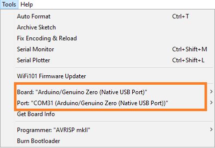
Next, we will need to select the relevant “Board” as well as “Port”. (Notice that I have also highlighted the necessary selections using an orange box.
- Board: “Arduino/Genuino Zero (Native USB Port)”
- Port: “COMXX” (this should be according to the COM port that is reflected on your machine. Mine is using COM31)
Alright! I know you have been eager to jump into the coding, so in the next step, that is what we will be focusing on.
Step 4: Time to Code
In this section, I will start by sharing code snippets from the completed project code. And at the end, I will publish the full source, making it easy for you to simply copy and paste the code into your Arduino IDE source file.
Header Files:
#include <xCore.h>     /* This is the library for the main XinaBox Core Functions. */
#include <xSW02.h>   /* This is the library for the VOC & Weather Sensor xChip. */
Defining some constants for controlling the RGB Led Signals:
#define redLedPin   A4
#define greenLedPin 8
#define blueLedPin  9
Next, we need to declare a function prototype for passing the RGB values.
void setRGBColor(int redValue, int greenValue, int blueValue);
Declaring the SW02 object:
xSW02 SW02;
The setup() method:
void setup() {

    // Start the I2C Communication
    Wire.begin();

    // Start the SW02 Sensor
    SW02.begin();

    // Delay for sensor to normalise
    delay(5000);

}
Now for the main loop():
void loop() {

    float tempC;

}
Next, we will need to poll using the SW02 object that we have created earlier in the program to start our communication with the sensor chip:
// Read and calculate data from SW02 sensor<br>SW02.poll();
Now, we are reading to get the sensor’s temperature reading.
tempC = SW02.getTempC();
Once we have the reading, the last thing that we are going to do is to use a series of if…else… control statements to determine the temperature range, and then call the setRGBColor() function.
// You can adjust the temperature range according to your climate. For me, I live in Singapore,
// which is tropical all year round, and the temperature range can be quite narrow here.

if (tempC >= 20 && tempC < 25) {
    setRGBColor(0, 0, 255);
} else if (tempC >= 25 && tempC < 30) {
    setRGBColor(0, 255, 0);
} else if (tempC >= 30 && tempC < 32) {
    setRGBColor(255, 190, 9);
} else if (tempC >= 32 && tempC < 35) {
    setRGBColor(243, 122, 0);
} else if (tempC >= 35) {
    setRGBColor(255, 0, 0);
}
Note: If you are interested to know what the relevant RGB values are for a particular color, I recommend you do a google search for “RGB color values”. There are plenty of sites available where you can use a color selector to pick the color that you want.
// If you like to, and it is optional, you can also add a delay in between polling for the sensor's readings.
delay(DELAY_TIME);
You can ofcourse declare the DELAY_TIME constant at the beginning of the program, that way, you only have to modify it’s value once rather than in multiple places throughout your program. Finally, we need the function to control our RGB LED:
void setRGBColor(int redValue, int greenValue, int blueValue) {
    analogWrite(redLedPin, redValue);
    analogWrite(greenLedPin, greenValue);
    analogWrite(blueLedPin, blueValue);
}
Final Program
include
include
define redLedPin A4
define greenLedPin 8
define blueLedPin 9
void setRGBColor(int redValue, int greenValue, int blueValue);
const int DELAY_TIME = 1000;
xSW02 SW02;
void setup() {
// Start the I2C Communication
Wire.begin();

// Start the SW02 Sensor
SW02.begin();

// Delay for sensor to normalise
delay(5000);
}
void loop() {
// Create a variable to store the data read from SW02<br>    float tempC;
tempC = 0;

// Read and calculate data from SW02 sensor
SW02.poll();

// Request SW02 to get the temperature measurement and store in the
// temperatue variable
tempC = SW02.getTempC();

if (tempC >= 20 && tempC < 25) {
    setRGBColor(0, 0, 255);
} else if (tempC >= 25 && tempC < 30) {
    setRGBColor(0, 255, 0);
} else if (tempC >= 30 && tempC < 32) {
    setRGBColor(255, 190, 9);
} else if (tempC >= 32 && tempC < 35) {
    setRGBColor(243, 122, 0);
} else if (tempC >= 35) {
    setRGBColor(255, 0, 0);
}

// Small delay between sensor reads
delay(DELAY_TIME);
}
void setRGBColor(int redValue, int greenValue, int blueValue) {
analogWrite(redLedPin, redValue);
analogWrite(greenLedPin, greenValue);
analogWrite(blueLedPin, blueValue);
}
Now that our program is ready, let’s program the xChip! The Upload process is exactly the same as how you would upload a program to your Arduino boards.
When you are done, why not unplug it and bring it out for a test run.
Check out the short time-lapsed video I created of myself testing the project in the outdoor. I also used the PB04 (Dual AA Intelligent Battery) xChip to power the project when it’s not connected to the laptop, making it compact and mobile.
I have also attached the Arduino project file in the next step. Feel free to download and run it! 🙂
Source: RGB Temperature Indicator (with XinaBox)