
Summary of RGB One Button USB Keyboard
This instructable shows how to build a tiny one-button RGB backlit USB keyboard using an ATtiny85 development board, a WS2812b LED, a Cherry MX compatible switch and keycap, a 3D printed case, and simple Arduino-based firmware. It covers required parts/tools, software setup, printing the enclosure, wiring and assembly, flashing configurable example code, and testing the finished single-key HID keyboard.
Parts used in the RGB One Button USB Keyboard:
- An ATtiny85 based development board (Digispark clone, smaller TINY85 version)
- WS2812b RGB LED (small round PCB or bare LED)
- Cherry MX or Cherry MX compatible switch (clear housing recommended)
- Cherry MX compatible keycap
- 3D printed case (STL files provided)
Ever felt the need to have a tiny, yet functional, RGB backlit keyboard, no bigger than the size of a single key? No? Who cares, make one anyway! This instructable will guide you through the steps you need to make your very own, slightly useless, one button keyboard.
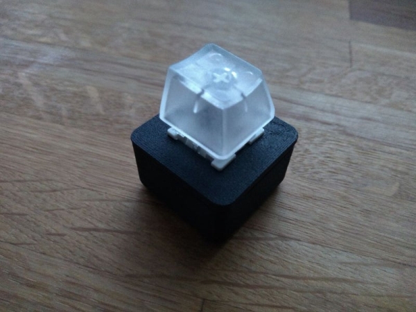
Step 1: Parts and Tools
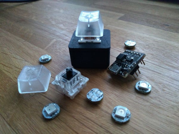
To make this project, you will need…
Parts:
- An ATtiny85 based development board. These boards are clones of the Digispark board, and can be bought for as little as 1-2GBP/USD. There are a few versions of this board, one which has a built in USB A connector, and two that have a built in Micro USB socket. The one needed for this project is the smaller of the two that has “TINY85” written on it as apposed to “ATTINY85”. All boards will function the same, but only this one will fit in the 3D printed case.
- A WS2812b RGB LED. These also come in different forms, the type needed are mounted on a tiny round PCB, little bigger than the LED itself. A bare LED can also be used, but bear in mind these will be very difficult to solder to.
- A Cherry MX/ Cherry MX Compatible switch. Switches with clear housings are ideal as they will allow the LEDS light to pass through.
- A Cherry MX compatible keycap.
Tools:
- A Soldering Iron and Solder will be needed. Flux, Solder Braid/Wick, a set of Third Hands, and more Flux are helpful too.
- A 3D printer is required to print the enclosure, but something similar can also be fasioned out of wood, acrylic, MDF, etc if you have access to basic hand tools. A case can also be cut out of a small ABS project box.
Step 2: Setting Up the Software
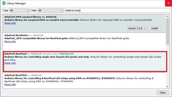
First, you will need to install the Arduino IDE and Digispark drivers. To do this, follow the instructions here. Upload the blink sketch included in the linked page, to make sure your board works. Next, you will need to install the Adafruit Neopixel Library, to control the led. In the Arduino IDE, go to Tools > Manage Libraries and search for “Adafruit Neopixel.” Download and install the library of the same name.
Step 3: Printing the Case
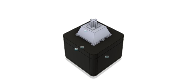
The STL files needed for the case and the example code can be downloaded from thingiverse here. Download and print the both parts of the case now, and make sure you hang on to the code – you’ll need that later.
Step 4: Wiring and Assembly
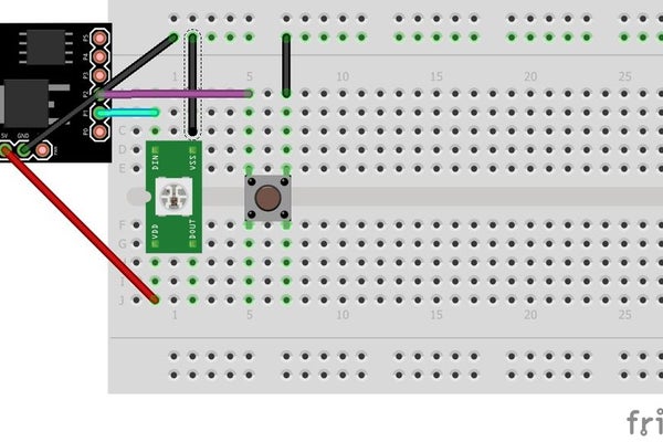
Wire up the components as shown in the diagram and images. The leds data pin should be connected to pin P1 on the board, and the switch should be connected to P2. Make sure you connect P1 to the leds data IN pin, and not the data OUT pin. Next, carefully insert the board into the case. Its a tight fit, and once its in, it will be very difficult to remove, so double check your wiring before hand. Then, line up the micro usb port with the corresponding cutout on the case, wedge a flathead screwdriver (or similar tool) behind the board and use it to push the socket into the cutout. It should fit in tightly. Use hotglue to hold the board in place. Finally, align the two indents in the top of the enclosure with the two protrusions in the base, and fit them together. Bear in mind that the case is NOT designed to be reopened after assembly, if unsure about your wiring, flash the code (as shown in the next step) and test the led and switch before fitting into the case.
Step 5: Flashing and Modifying the Code.
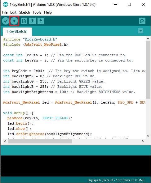
Unzip the example code you downloaded from Step 3, and open it in the Arduino IDE. This simple sketch allows you to set the backlight to your desired colour, and map a key to the switch. Modify the variables backlightR,G and B to pick the colour you would like the backlight to be, and backlightBrightness to modify the intensity of the led. All four of these variables must have a number from 0 (off) to 255 (maximum). To map a key, modify the variable “keyCode” to with whichever key you like. A list of keycodes can be found here. Once you have modified the code to your liking hit the upload button, to compile and flash the code to your board. Once its done compiling, the terminal will prompt you to plug in your board. Make sure you plug it in within 60 seconds, or you will have to repeat the upload process.
Step 6: Done!
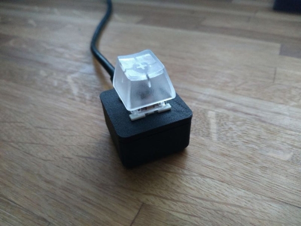
You should now have a fully functional single key keyboard! The provided code mimics a regular USB HID keyboard, so it can be used without any installing additional software, though you can download macro programs such as AutoHotkey to automate actions when you press the key. If you want to customize the code more than what is offered by the example code, you can write your own using the Digikeyboard library. The FastLED library can also be used to control the led and offers much more powerful functions than Adafruit_Neopixel.
If you liked this instructable, please consider voting for it in the Big and Small Contest, have fun making!
Source: RGB One Button USB Keyboard
- What development board is required?
An ATtiny85 based development board (Digispark clone) the smaller TINY85 version that fits the 3D printed case. - Which LED is used for the backlight?
A WS2812b RGB LED mounted on a tiny round PCB (a bare LED can also be used). - Which pins are used for the LED and switch?
The LED data pin connects to pin P1 and the switch connects to P2 on the board. - How do I set up the software libraries?
Install the Arduino IDE, Digispark drivers, then install the Adafruit Neopixel library via Tools > Manage Libraries. - Where do I get the case files and example code?
Download the STL files and example code from the Thingiverse link provided in the instructable. - How do I change the backlight color and brightness?
Modify backlightR, backlightG, backlightB (0–255 each) and backlightBrightness (0–255) in the example sketch. - How do I map a key to the switch?
Change the keyCode variable in the example sketch to the desired keycode from the supplied keycode list link. - What libraries can be used for more LED control?
The FastLED library can be used for more powerful LED control beyond Adafruit Neopixel. - Can the case be reopened after assembly?
No, the case is not designed to be reopened; test wiring and firmware before final assembly.
