Summary of RGB LED Color Selector / Picker / Chooser
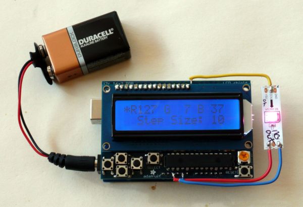
This project builds a handheld RGB LED color picker using an Arduino and an Adafruit 16x2 LCD shield with buttons to adjust red, green, and blue values, driving a single WS2812b addressable LED soldered to the shield. It shows wiring: Arduino digital pin 6 to the LED data-in, plus 5V and GND to the LED power, and suggests diffusing the bright LED with paper or aiming it at a white surface.
Parts used in the RGB LED Color Selector / Picker / Chooser:
- Arduino (or clone)
- Adafruit LCD Shield (16x2 display with 5 push buttons)
- WS2812b digitally addressable LED (single, from a strip or on carrier board)
- Solid core wire (20 gauge suggested)
- Soldering tools and solder
- Optional: piece of white paper for diffusion
One Challenge with working with RGB LEDs is getting the right Red, Green and Blue values to match a color you are trying to display. You can start with web colors, and then sometimes need to adjust them since the LEDs don’t look quite the same as they do on monitors.
 So, this is a quick project to allow you to set the RGB values with a simple hand-held gadget – maybe useful when working offline with these LEDs.
This project shows a WS2812b digitally addressable LED, but could be adapted for other LED types.
Parts:
- An Arduino – clones can be found for $10
- An Adafruit LCD Shield – this shield has a 16×2 LED display, and 5 push buttons that we will use for changing the red, green, and blue color values. Adafruit also has a shield where the backlight color is an RGB LED – might be worth trying!
- An LED – this one uses a single WS2812b LED from a 30 LED/meter strip of LEDs – we had this left over from another project. Adafruit sells them individually on carrier boards too.
- Some solid core wire – I used some 20 gauge wire since it was rigid and held the LED nicely.
Step 1: Construction
Build the LED Shield per the instructions that come with it (online). Test it our with your Arduino.
Now, we will solder the LED to the board. Since the LCD Shield is intended to be on the top of the stack of shields, the pins are not brought out in header sockets. But the pins are there to mechanically support the shield, so you can carefully solder wires to the tops of those pins. See the pictures for details.
We will solder digital pin 6 to the data in line – that has to be connected to the input end of the arrow on the LED since they have a direction on the data line. The other two wires are the +5v, and Gnd – those can be soldered on either end of the LED.
The LED is very bright, so one idea is to put a piece of white paper over it. Or perhaps aim it down and run it over a white surface.
For more detail: RGB LED Color Selector / Picker / Chooser
- What is the purpose of the project?
To create a handheld gadget to set RGB values for an LED using an Arduino and an Adafruit LCD shield. - Which Arduino pin is used for LED data?
Digital pin 6 is soldered to the LED data in line. - Which LED type is used in the project?
The project uses a single WS2812b digitally addressable LED. - How are power connections made to the LED?
The LED is connected to +5V and GND soldered to either end of the LED. - How are the LCD shield buttons used?
The five push buttons on the Adafruit LCD shield are used to change the red, green, and blue color values. - Can clones of the Arduino be used?
Yes, Arduino clones can be used and can be found for about $10. - How should the LED be positioned or diffused because it is bright?
The LED can be covered with a piece of white paper or aimed down over a white surface to reduce brightness. - Where should wires be soldered on the LCD shield?
Carefully solder wires to the tops of the shield's mechanical support pins since header sockets are not brought out.