Summary of Aqua Garduino Mini @hydroFishAqua82
Arduino Powered Micro Aquaponic System with Pi Camera and Twitter Feed — concise summary: An automated aquaponic system using an Arduino for sensors and motors and a Raspberry Pi for orchestration and Twitter updates (images, sensor data, alerts). Built around a Brita filter with plants on top and fish below; includes lights, pumps, stepper motor, relays, sensors, and an LCD. pH sensor was not integrated by the due date.
Parts used in the Arduino Powered Micro Aquaponic System with Pi Camera and Twitter Feed:
- Arduino Inventors Kit refill pack
- 4.7K Ohm resistors (2)
- Raspberry Pi
- Arduino Mega
- Pi camera
- Brita filter
- Perlite
- Water pump
- Air pump
- Tubing for air pump
- Tubing for water pump (2)
- CFL light bulbs
- Electrical wire (2)
- Glass dropper bottle
- Zip it wall board anchor (2)
- 5 volt DC stepper motor with driver board
- Net pots (10 pack)
- Plants (6)
- Tetra neon fish (5)
- Fish food
- 15 Amp outlet
- Adhesive Velcro
- Wirenuts (bag of 25)
- USB outlet (2)
- pH circuit for Arduino
- Aquarium Hydroponic PH controller meter Electrode Probe BNC Connector
- BNC Connector - Right Angle
- One Wire Digital Temperature Sensor - DS18B20
- 365buying DS18B20 Waterproof Digital Thermal Probe Sensor DS18B20
- AC power plug
- 4 wire (8 feet) AWG 18
- Water conditioner
- Cutequeen 30cm LED Car Flexible Waterproof Light Strip White (pack of 4)
- LCD 16x2
- Electrical Red Black RL1-3 3 Pin SPST Rocker Switch
- 2x4 lumber
We are creating an automated aquaponic system with mobile updates via Twitter. Sensors and motors will be controlled from an Arduino while the entire system, including mobile updates, will be orchestrated by a Raspberry Pi. Tweets include pictures, sensor data, and system-critical updates. Original system schematics have changed a little but not much. We only used (2) relays and the LCD was attached to the Arduino, and the pH sensor didn’t make it into the system as of our due date.
Step 1:
Parts List
- Arduino Inventors Kit refill pack https://www.sparkfun.com/products/11479
- 4.7K Ohm resistors (2) http://www.amazon.com/E-Projects-4-7k-Resistors-Wa…
- Raspberry Pi http://www.adafruit.com/products/998?gclid=CIizqL…
- Arduino Mega http://www.adafruit.com/products/998?gclid=CIizqL…
- Pi camera http://www.adafruit.com/products/998?gclid=CIizqL…
- brita filter http://www.adafruit.com/products/998?gclid=CIizqL…
- perilite http://www.adafruit.com/products/998?gclid=CIizqL…
- water pump http://www.adafruit.com/products/998?gclid=CIizqL…
- air pump http://www.adafruit.com/products/998?gclid=CIizqL…
- tubing for air pump http://www.adafruit.com/products/998?gclid=CIizqL…
- tubing for water pump (2) http://www.adafruit.com/products/998?gclid=CIizqL…
- CFL light bulbs http://www.adafruit.com/products/998?gclid=CIizqL…
- electrical wire (2) http://www.adafruit.com/products/998?gclid=CIizqL…
- glass dropper bottle http://www.adafruit.com/products/998?gclid=CIizqL…
- zip it wall board anchor (2) http://www.adafruit.com/products/998?gclid=CIizqL…
- 5 volt DC stepper motor with driver board http://www.adafruit.com/products/998?gclid=CIizqL…
- net pots (10 pack) http://www.adafruit.com/products/998?gclid=CIizqL…
- plants (6) http://www.adafruit.com/products/998?gclid=CIizqL…
- tetra – neon (5) http://www.adafruit.com/products/998?gclid=CIizqL…
- fish food http://www.adafruit.com/products/998?gclid=CIizqL…
- 15 Amp outlet http://www.adafruit.com/products/998?gclid=CIizqL…
- adehesive Velcro http://www.adafruit.com/products/998?gclid=CIizqL…
- wirenuts (bag of 25) http://www.adafruit.com/products/998?gclid=CIizqL…
- usb outlet (2) http://www.adafruit.com/products/998?gclid=CIizqL…
- pH circuit for Arduino http://www.adafruit.com/products/998?gclid=CIizqL…
- Aquarium Hydroponic PH controller meter Electrode Probe BNC Connectorhttp://www.adafruit.com/products/998?gclid=CIizqL…
- BNC Connector – Right Angle http://www.adafruit.com/products/998?gclid=CIizqL…
- One Wire Digital Temperature Sensor – DS18B20http://www.adafruit.com/products/998?gclid=CIizqL…
- 365buying DS18B20 Temperature Sensor – Waterproof Digital Thermal Probe Sensor DS18B20 http://www.adafruit.com/products/998?gclid=CIizqL…
- AC power plug http://www.adafruit.com/products/998?gclid=CIizqL…
- 4 wire (8 feet) AWG 18 http://www.adafruit.com/products/998?gclid=CIizqL…
- water conditioner http://www.adafruit.com/products/998?gclid=CIizqL…
- Cutequeen 30cm LED Car Flexible Waterproof Light Strip White (pack of 4)http://www.adafruit.com/products/998?gclid=CIizqL…
- LCD 16×2 http://www.adafruit.com/products/998?gclid=CIizqL…
- Electrical Red Black RL1-3 3 Pin SPST Rocker Switchhttp://www.adafruit.com/products/998?gclid=CIizqL…
- 2×4 lumber http://www.adafruit.com/products/998?gclid=CIizqL…
Step 2: Schematic of System
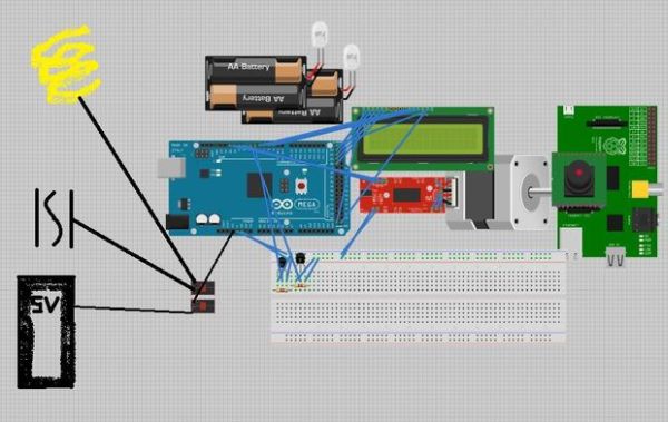
Find our code on github!: https://github.com/vermiculus/garduino
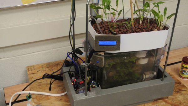
Step 3: System Skeleton
Our system is built around a brita filter. The bottom will support the fish, and on top we will put the plants. We built a frame around the filter it to attach lights and wires. The bottom is made out of plywood, and we attached four poles in drill holes in the corners of the 2×4 that come together high above the filter to hang the lights from. In the bottom of the frame we left an open space to use for wire storage so that we have a place for the microcontroller boards and the alike to go.
For more detail: Aqua Garduino Mini @hydroFishAqua82
- What controls sensors and motors in the system?
Sensors and motors are controlled from an Arduino. - What orchestrates the system and mobile updates?
The Raspberry Pi orchestrates the entire system and handles mobile updates via Twitter. - What does the Twitter feed include?
Tweets include pictures, sensor data, and system-critical updates. - Was the pH sensor integrated into the system?
The pH sensor did not make it into the system by the due date. - How is the physical system constructed?
The system is built around a Brita filter with fish below and plants on top, and a frame of 2x4s to hang lights and store wires and electronics underneath. - Where can the project code be found?
The code is available on GitHub at https://github.com/vermiculus/garduino. - How many relays were used?
The system used two relays. - Where was the LCD attached?
The LCD was attached to the Arduino.