Summary of RGB Backlight + MSGEQ7 Audio Visualizer
This article guides users in building an RGB LED backlight for TVs or desks using an Arduino Nano and WS2812 strips. It details the hardware setup, including optional audio visualization via an MSGEQ7 analyzer, wiring instructions, and code logic for various lighting modes like rainbow fades and music analysis. The project allows brightness control via a potentiometer and mode switching via a push button, with specific notes on PC audio configuration to enable simultaneous speaker output and signal processing.
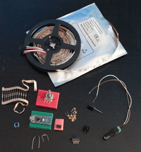
Parts used in the RGB LED Backlight + MSGEQ7 Audio Visualizer:
- Arduino Nano/Uno
- WS2812 RGB LED Strip
- 5V Power Supply
- 3.5mm Audio Jack
- Potentiometer 10kOhm
- Push Button
- Resistors (1x 10kOhm, 1x 220Ohm, 2x 100kOhm)
- Capacitors (1x 1000uF Electrolytic, 2x 10nF, 2x 0.1uF, 1x 33pF)
- Simple Diode
- DC Jack
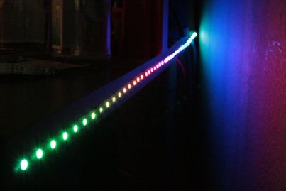
Welcome to my Instructables on how to build a RGB LED backlight for e.g. the back of your TV or desk.
The Schematic itself is very simple since the WS2812 LED Strips are very easy to interface with e.g an Arduino Nano.
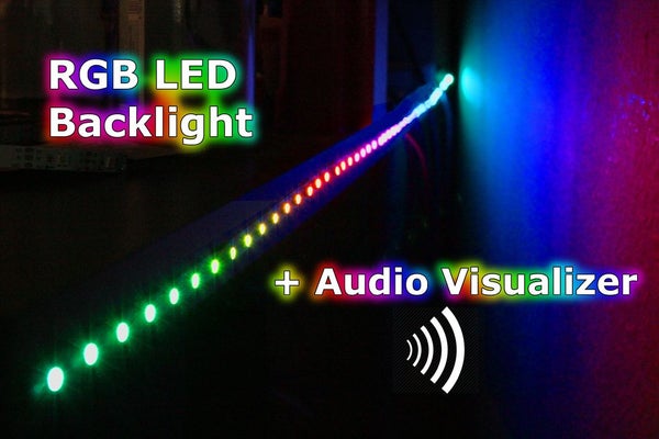
Note: that you do not have to use the additional MSGEQ7 Audio Analyzer circuit if you only want the LED Backlight without audio visualization.
I provided a detailed list of the used parts and where you can buy them:
- Arduino Nano/Uno ( Amazon / AliExpress )
- WS2812 RGB LED Strip ( Amazon/ AliExpress ), note that IP stands for the protection (e.g. waterproof if you need) and the number stands for how many LEDs per Meter the strip has ( important for power supply)
- 5V Power Supply ( Amazon )(depens how many LEDs strip has) -> each LED takes ~20mA, the strip used in this instructable has 45 LEDs (30 per Meter) so I need 45*20mA ~ 1,5Ampere supply (Arduino,MSGEQ7 need some too), I linked a power supply which provides 3A which is definetely enough for us now
- 3.5mm Audio Jack ( Amazon / AliExpress )
- Potentiometer 10kOhm ( Amazon / AliExpress )
- Push Button ( Amazon / AliExpress )
- Resistor (1x 10kOhm, 1x 220Ohm, for MSGEQ7: 2x100kOhm)
- Capacitors (1x 1000yF Electrolytic ( Amazon / AliExpress ) , 2x 10nF , for MSGEQ7: 2x 0.1yF , 1x33pF ( Amazon / AliExpress )
- Simple Diode (Amazon / AliExpress )
- DC Jack ( Amazon / AliExpress )
Step 1: Build the Schematic
Main Schematic:
So to interface the WS2812 Strip with an Arduino is pretty straight forward using the Adafruit_NeoPixel library.
The LED Strip has 3 Pins: VCC, DATA, GND. VCC is connected to 5V, GND to Ground and the DATA Pin in the middle is connected to LED_DATA Pin D6 on the Arduino. Now every LED on the Strip has an WS2812 chip on it which takes in the Data it receives from the Arduino and passes it on to the next LED, therefore we only need to feed the Led data once to the first LED on the strip.
The logic of the Push Button to change the modes and the Potentiometer to control Brightness is explained in the next Step.
The exact Schematic can be found in the Screenshot of the fritzing file which is also available to download.
Note that it is very important to only connect the Arduino 5V Pin to the Power Supply via the diode , so that the Arduino is not damaged if we plug in the USB Cable to program it. The 10nF and 1000uF is also for safety reasons, so that there won’t be any Power shortages.
For the MSGEQ7 Circuit:
This is the most common Circuit to connect a MSGEQ7 to an Arduino. This is also where you need the 3.5mm audio Jack. The middle pin of most audio Jacks is GND, the pins on the left/right are the stereo channels which connect via an 10nF capacitor to the Signal In Pin of the MSGEQ7 as shown in the schematic. You can additionally add a potentiometer to the Signal In Pin to control the sensitivity of the Audio Signal, but is really not necessary. The MSGEQ7 is connected to the Arduino with Analog Out pin connected to A1 (MSGEQ_OUT), Strobe Pin to D2 (STROBE), Reset Pin to D5 (RESET).
Step 2: The Code
GitHub Link to complete Sketch:RGBStripe_Control_WS2812
Notes on the code:
In the code we declare the WS2812 Strip object with a new Adafruit_NeoPixel object, passing in the number of Leds (change NUM_LEDS for you setup), the Arduino Pin connected to the LED_DATA pin, and the coding type + speed of the color values transmission.
Once this is done we set the default Brightness in setup() via setBrightness(0-255) and turn on the Strip with begin(). We can now set each individual Pixel/LED to a specific RGB Color with setPixel(LED, Color). When we are done set all LEDs to new values we update the strip with strip.show(). That is basically all the code logic we need to programm any animation we want. Now to actually control the Animations/Modes we add a Push Button / Tactile Switch to the Arduino. We Therefore connect one end of the Button to VCC and the other to Arduino Pin D3 and with a 10kOhm resistor to GND. We attach an Interrupt to this Pin in the setup(), which triggers a call to the changeMode() method every time we press the button. In changeMode() we simple toggle to the next mode and tell the current animation to break. Once that happens the loop() is newly executed and will play the new Animation/Mode.
The provided Animations include: Rainbow color fade, Red, Green, Blue, White Color , Music analyzer mode
Additionally I added a 10kOhm Potentiometerto control the brightness of the Strip. the method checkBrightness() checks the output of the Potentiometer connected to Pin A2 (middle Pin of Potentiometer) and updates the Strip’s brightness accordingly.
For musicAnalyzer() mode via MSGEQ7 :
This mode visualizes the Audio Signal connected to Signal In of the MSGEQ7. The MSGEQ outputs a analog Signal showcasing a single audio band ( 8 Bands, from Low to High frequencies). The musicAnalyzer() method gets the current values of the audio bands by resetting the MSGEQ and then buffering the analog values provided. The band being outputted can be changed by putting a high flank on the Strobe Pin. After all the 8 Bands have been buffered the method shifts all the LED Pixel values one backand calculates the new Value for LED 0. The color is comprised of : Low frequency(Bass) Red Color, Middle frequency Green Color and High frequency Blue color. The shifting of the value before loading the new value gives us a nice smoothly timed animation.
Step 3: Setup Audio on PC
To get your music/audio fed into the MSGEQ7 but still having your music play on your speakers, you either have to use the RealtekHD Stereomix feature or connect the MSGEQ Audio Input to e.g. rear speaker output of your soundcard/motherboard.
To enable the Stereomix in Win10, right click the speaker icon on the bottom right and click “Sounds”, here you can activate Stereomix in the “Recording” Tab (right click -> activate). If the Stereomix is not visible, right click an choose “Show disabled devices”. Now open the settings for the Stereomix and tell it to listen and copy the audio of your main Speakers.
If you want to use the rear speaker output, open the settings of you main speaker in the “Sounds” menu, Tab “Improvements” and then select “Environment” from the list and choose “Room” in the dropdown menu below.
This now enables parallel audio output of your speakers and the MSGEQ7.
Step 4: Notes
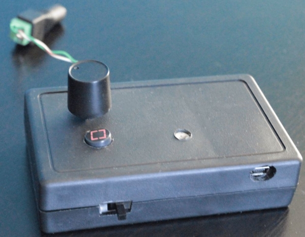
Since the schematic is no that complicated nor big in size I managed to put the entire circuitry into a little box with holes for the USB connector,Audio Jack, DC Jack, Potentiometer and Push Button. You can simply use male/female pin headers and connect the 3 Cables to the WS2812 Strip via Jumper cables.
Source: RGB Backlight + MSGEQ7 Audio Visualizer
- How do I connect the WS2812 LED Strip to the Arduino?
VCC connects to 5V, GND to Ground, and the DATA pin connects to Arduino Pin D6. - Can I use this project without audio visualization?
Yes, you do not need the MSGEQ7 Audio Analyzer circuit if you only want the LED Backlight. - What is the best way to calculate the power supply requirements?
Each LED takes ~20mA; for a strip with 45 LEDs, you need approximately 1.5A plus extra for the Arduino and other components. - Does the diode prevent damage when programming the Arduino?
Yes, connecting the Arduino 5V Pin to the Power Supply via a diode prevents damage if the USB cable is plugged in. - How does the push button change the lighting modes?
An interrupt attached to Pin D3 triggers the changeMode method to toggle to the next animation every time the button is pressed. - How can I control the brightness of the strip?
A 10kOhm Potentiometer connected to Pin A2 checks the output to update the strip's brightness accordingly. - What colors represent different frequencies in music analyzer mode?
Low frequency (Bass) is Red, Middle frequency is Green, and High frequency is Blue. - How do I enable parallel audio output on Windows 10?
You must activate the RealtekHD Stereomix feature in the Recording tab settings to listen and copy audio from main speakers.