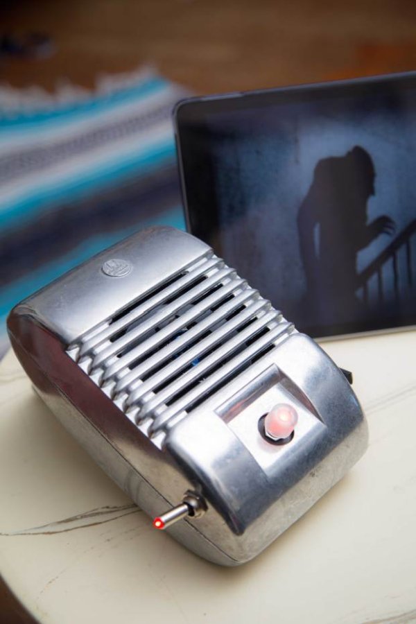
When I was a kid we went to the drive-in theater to see movies like The Legend of Boggy Creek and Evel Knievel. I loved those movies but I remember just as vividly those retro-cool metal speakers that entered into our car for these campy films. A few years ago I found one of these speakers at a flea market and it came home with me.

After it sat in my garage for years, I finally decided it needed to be what it was made to be: a speaker. But this time it gets some pretty nice power and technology, as a 20-watt amplified stereo speaker set with an RGB lighted dial that first dials in your volume by color and then, with a click, pulses to the beat of the music. It’s all done with 4 modern off-the-shelf circuit boards inside — but to keep the retro look, there’s an old-school toggle switch for power.
Another thing I really like about this project is that we take some off-the-shelf maker kit work and apply it to a gift from the past and make it new again.
Hardware
Arduino Pro Mini: As with most of my hardware projects, I start with a standard Arduino. Of course, the standard Arduino board isn’t going to fit into this case and designing a custom board is time-consuming and expensive. The solution for many projects is to use one of the small Arduino boards available. I used the Arduino Pro Mini and it was perfect for this project. It’s inexpensive, very small, and reliable.
Adafruit Stereo 20W Class D Audio Amplifier – MAX9744 board: One of the things I really needed for this project was the ability to control the volume digitally. After hunting for a while I settled on the Ada Fruit MAX9744 board. This beautiful little board gave me everything I needed in a small package and it sounds awesome.
Adafruit Electret Microphone Amplifier: This optional finishing touch provides modulation of the color of the LED to the beat of the music. This is accomplished by using this little mic board to listen to the music, then filtering the analog signal to detect the beat (thanks to some existing open source Arduino software). This mode is enabled and disabled by clicking the encoder. If this mode is not wanted, simply omit it from the project and everything else will work just fine as-is.
Sparkfun RGB Encoder breakout board: This little board makes the addition of the RGB encoder easy for this project.
1. Build the Adafruit Amplifier
Follow the manufacturer’s instructions for Digital Input, except don’t install all the header pins; install only those for SDA, SCL, Vi2c, SHDN, Mute, GND, and VDD (Figure A).
2. Prepare the Arduino Pro Mini
Solder the headers on (Figure B), then download the project code file DriveIn.ino, and upload it to the Arduino.
TIP: Find or draw a diagram of the pin markings on the Arduino, because they’re difficult to see after the headers are installed.
3. Solder RGB encoder to breakout
Insert the encoder into the side of the board labeled RGB, then solder the headers on the opposite side, labeled RG (Figure C).
NOTE: It’s easy to mistakenly use the wrong side of the encoder breakout board. Be sure to assemble as shown.
Read More: Revive Old Drive-In Speakers with a Modern LED Twist
