This article is the 12th in a series on home automation Instructables documenting how to create and integrate an IoT Retro Speech Synthesis Device into an existing home automation system including all the necessary software functionality to enable the successful deployment within a domestic environment.
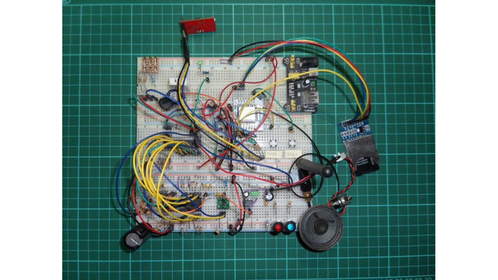
Picture 1 shows the completed IoT speech synth device and Picture 2 shows all the component parts used in the prototype which were form factor reduced to go into the final product.
The video shows the device in action (during testing).
Introduction
As mentioned above this Instructable details how to make an IoT Retro Speech Synthesis Device and is based around the General Instruments SP0256-AL2.
It’s primary purpose is add ‘old school’ voice synthesis to an IoT network. Why ‘old school’ you may ask? Well, because I was around in the 80’s when these things were first manufactured and I interfaced one to my BBC Micro so for me there’s some degree of nostalgia surrounding the SP0256-AL2.
I much prefer the challenge of trying to figure out what on earth is being said by this Dalek sounding voice than listening to the dulcet tones of a hipster Amazon echo or Siri. Where’s the challenge in that I ask you?
Oh, and not to mention I also have a ‘bag load’ of ‘SP0256-AL2’ ICs lying around.
The device is also capable of reading local temperature and humidity so further extends the ambient instrumenting of my existing IoT infrastructure hooking into the MQTT/OpenHAB based IoT network detailed in this series on home automation (HA), building on reused code taken from here.
At it’s heart is an ESP8266-07 which is responsible for MQTT communications and controlling all system functionality (SD card access, led control, temperature/humidity sensing, volume control, speech synthesis).The device is fully configurable via text files stored on a local SD card, though calibration and network security parameters can also be programmed via remote MQTT publications.
What parts do I need?
See the bill of materials here
What software do I need?
- Arduino IDE 1.6.9,
- Arduino IDE configured to programme the ESP8266-07 (same as this). Then configure the IDE as indicated in the detailed description provided in the software sketch here,
- Python v3.5.2 if you wish to use the automated test capability, details here
What tools do I need?
- Microscope at least x3 (for SMT soldering),
- Molex connector crimping tool (for JST connectors),
- SMD soldering Iron (with liquid flux pen and flux cored solder),
- Screwdrivers (various),
- Heat gun,
- Drills (various),
- Countersink handtool,
- Files (various),
- Dremel (various bits),
- Sturdy vice (small and large, like a black and decker work mate),
- Scalpel,
- Vernier calipers (used to measure fabrication and useful for sizing PCB components),
- Spanners and Nut drivers (various),
- Strong tweezers (for SMT soldering),
- Junior Hacksaw,
- Drill (with various drill bits),
- Fine pliers (point and snub nosed),
- Flush cutters,
- DMM with audible continuity check,
- Dual channel digital scope (handy for debugging signals)
What skills do I need?
- A lot of patience,
- A great deal of manual dexterity and excellent hand/eye coordination,
- Excellent soldering skills,
- Excellent fabrication skills,
- The ability to visualise in 3 dimensions,
- Some knowledge of software development with ‘C’ (if you want to understand the source code),
- Some knowledge of Python (how to install and run scripts, if you want to use the automated testing),
- Knowledge of Arduino and it’s IDE,
- Good knowledge of electronics,
- Some understanding of your home network.
Topics Covered
- User Manual
- Circuit Overview
- PCB Manufacture and Assembly
- Fabrication
- Software System Overview
- Software Overview
- Sensor Calibration
- MQTT Topic Naming Convention
- Debug & Fault Finding
- Testing the Design
- Conclusion
- References Used
Series Links
To Part 11 : IoT Desktop Console. Part : 11 IoT, Home Automation
Step 1: User Manual
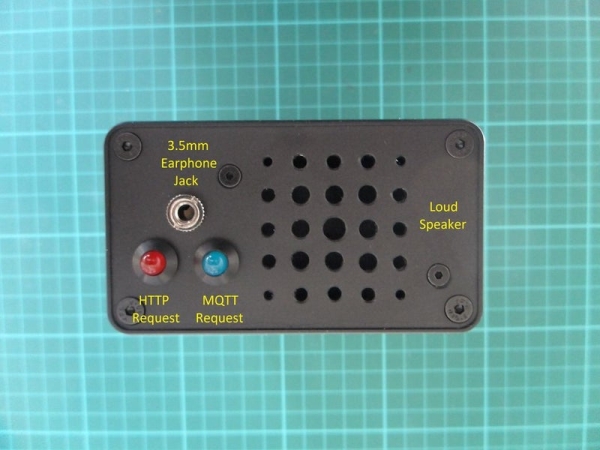
Picture 1 above shows the front of the Retro Speech Synthesiser and picture 2 the rear.
Enclosure Front
- Speaker Grill
- 3.5mm Earphone Jack : The main speaker is disabled when 3.5mm jack is inserted.
- Red LED : This LED illuminates whilst a word is being spoken when speech was initiated via an HTTP request.
- Blue LED : This LED illuminates whilst a word is being spoken when speech was initiated via an MQTT IoT request.
Enclosure Rear
- Reset Button : Used to hard reset the ESP8266-07 IoT device.
- Flash Button : When used in conjunction with the Reset Button allows re-flashing of the ESP8266-07.
- WiFi Antenna plug (SMA Plug) : For external WiFi Antenna giving the least RF path attenuation as the closure is aluminium.
- External Programming Port : To remove the need to unscrew the enclosure to gain access to the ESP8266-07 for re-programming purposes. The programming pins of the ESP8266-07 have been brought out to the external programming port. Picture 3 is the programming adapter.
- Green LED : This is the IoT system led and is used to indicate diagnostic status of the device and boot up and whilst operating.
- External Temperature/Humidity Sensor (AM2320)
- SD Card slot : This holds all config/security data along with web server pages.
- 2.1mm Supply jack 6vdc
Step 2: Circuit Overview
The Retro Speech Synth device comprises two PCBs;
- RetroSpeechSynthIoTBoard : This is a generic, re-usable ESP8266-07/12/12E/13 PCB
- RetroSpeechSynthBoard : This is a generic SP0256-AL2 PCB
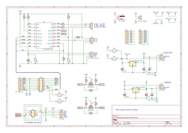
Retro Speech Synth IoT Board
This board allows for either the direct soldering of an ESP8266-07/12/12E/13 or 0.1″ pitch sockets accommodating an ESP8266 carrier PCB.
The board was designed to expand it’s I/O over an I2C connection and can support either 3v3 or 5v supply levels via Q1, Q2, R8-13.
Connection to the board is achieved via one of two headers J2 and J4, An 8-way DIL IDC ribbon or 5-way JST/Molex.
U2 and U3 provision 3.3v and 5v on board supply regulation. Alternatively if greater current capacity is required, off board serial shunt regulators may be attached via connectors J10 and J11 respectively.
Connectors J1 and J3 offer external SD card support over SPI. J1 has been designed for an 8-way Molex and J3 has direct pin for pin compatibility support for an off the shelf SD card PCB with either 3v3 or 5v support.
Retro Speech Synth Board
Control of this board is over an I2C 5v compliant connection via J1, J5 or J6, a 4-way JST/Molex, 8-way DIL IDC or 8-way IDC ribbon connector.
U2 MPC23017 provides the I2C to parallel interface to U3 the SP0256-AL2 and LEDS D1 (Green), D2 (Red) and D3 (Blue). The output of the Speech Synth is fed to audio amp CR1 TBA820M via either analogue pot RV1 or digital pot U1 MCP4561.
Digital Pot U1 is also controlled via 5v compliant I2C.
Note : The ESP8266-07 device was chosen as it has an integral IPX RF connector allowing an external WiFi Antenna to be added to the aluminum enclosure.
Step 3: PCB Manufacture and Assembly
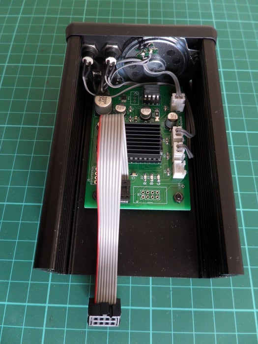
Pictures 1 and 2 show the completed and wired PCB sub-assemblies located on the aluminum enclosure substrate.
The two PCBs were designed using Kicad v4.0.7, manufactured by JLCPCB and assembled by me and shown above Pics 3 to 13.
Step 4: Fabrication
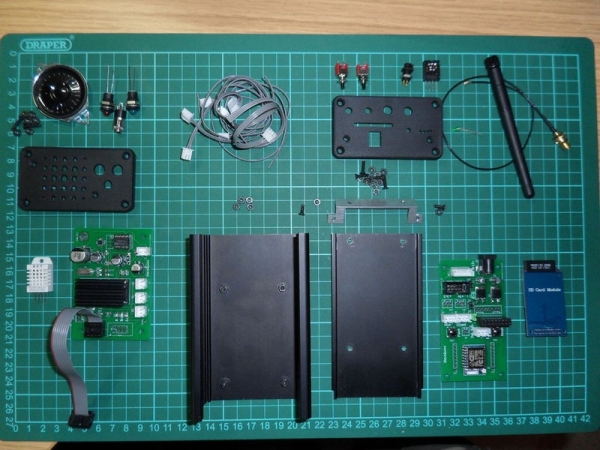
Picture 1 shows a Haynes Manual style layout of all the prefabricated parts before final assembly.
Pics 2 … 5 show various shots during the fabrication of the enclosure with minimal clearances.
Step 5: Software System Overview
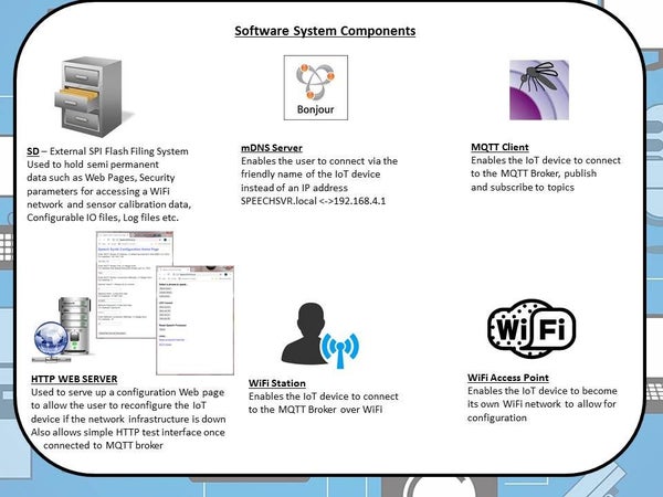
This IoT Retro Speech Synthesis Device contains six key software components as shown in pic 1 above.
SD Card
This is the external SD SPI Flash Filing System and is used to hold the following information (see pic 2 above);
- Icons and ‘Speech Synth Configuration Home Page’ index.htm: Served up by the IoT device when it is unable to connect to your IoT WiFi network (usually due to incorrect security information, or first time use) and provides the user with a means of remotely configuring the sensors without the need to re-flash new SD content.
It also holds index1.htm, mqtt.htm and sp0256.htm, these are the locally served web pages accessible over a web browser allowing limited control of the speech synth over HTTP. - Security Information: This holds the information used at power up by the IoT device to connect to your IoT WiFi network and MQTT Broker. Information submitted via the ‘Speech Synth Configuration Home Page’ is written to this file (‘secvals.txt’).
- Calibration Information: The information contained within the files (‘calvals1.txt’ and ‘calvals2.txt’) are used to calibrate the on-board temperature/humidity sensors should it be necessary. Calibration constants can be written to the IoT device via MQTT commands from an MQTT broker or by re-flashing the SD card. ‘calvals1.txt’ pertains to the AM2320 sensor and ‘calvals2.txt’ to the DHT22.
- User configurable system values: The information contained within this file (‘confvals.txt’), chosen by the user, controls certain system responses, such as initial digital volume level, auto ‘system ready’ announcement on MQTT broker subscription etc.
mDNS Server
This functionality is invoked when the IoT device has failed to connect to your WiFi network as a WiFi station and instead has become a WiFi access point something akin to a domestic WiFi router. In the case of such a router you would typically connect to it by entering the IP Address of something like 192.168.1.1 (usually printed on a label affixed to the box) directly into your browser URL bar whereupon you would receive a login page to enter the username and password to allow you to configure the device. For the ESP8266-07 in AP mode (Access Point mode) the device defaults to the IP address 192.168.4.1, however with the mDNS server running you only have to enter the human friendly name ‘SPEECHSVR.local’ into the browser URL bar to see the ‘Speech Synth Configuration Home Page’.
MQTT Client
The MQTT client provides all the necessary functionality to; connect to your IoT network MQTT broker, subscribe to the topics of your choice and publish payloads to a given topic. In short it provisions IoT core functionality.
HTTP Web Server
This web server has two purposes;
- If the IoT device is unable to connect to the WiFi network whose SSID, P/W etc. is defined in the Security Information file held on the SD Card the device will become an Access Point. Once connected to the WiFi network provided by the Access Point, the presence of an HTTP Web Server allows you to directly connect to the device and change it’s configuration via the use of an HTTP Web Browser it’s purpose being to serve up the ‘Speech Synth Configuration Home Page’ web page which is also held on the SD Card.
- Once the IoT Retro Speech Synthesis Device has connected to the WiFi network and MQTT broker, if accessed, the HTTP Web Server will automatically serve up an HTTP web page allowing limited control of the IoT device to speak a selection of fixed phrases and the ability to cycle the two front Red and Blue LEDS.
WiFi Station
This functionality gives the IoT device the capability to connect to a domestic WiFi network using the parameters in the Security Information file, without this your IoT device will not be able to subscribe/publish to the MQTT Broker.
WiFi Access Point
The ability to become a WiFi Access Point is a means by which the IoT device allows you to connect to it and make configuration changes via a WiFi station and a browser (such as Safari on the Apple iPad). This access point broadcasts an SSID = “SPEECHSYN” + the last 6 digits of the MAC address of the IoT device. The password for this closed network is imaginatively named ‘PASSWORD’
Step 6: Software Overview
Preamble
To successfully compile this source code you will need a local copy of the code and libraries outlined below in Step 12, References Used. If you are not sure how to install an Arduino library go here.
Overview
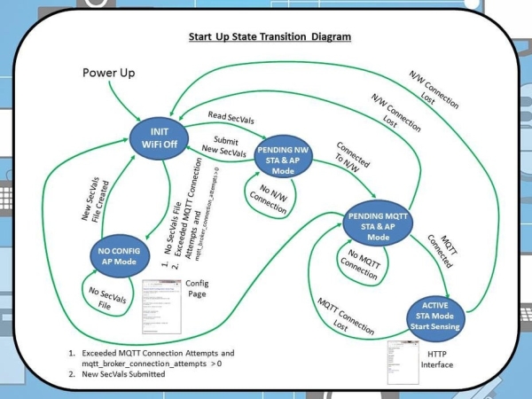
The software makes use of the state-machine as shown in pic 1 above (full copy of source in my GitHub repository here). There are 5 main states as outlined below;
- INIT
- This initialisation state is the first state entered after power up.
- NOCONFIG
- This state is entered if after power up an invalid or missing secvals.txt file is detected. During this state the Config Page is visible.
- PENDING NW
- This state is transitory, entered whilst there exists no WiFi network connection
- PENDING MQTT
- This state is transitory, entered after a WiFi network connection has been made and whilst there exists no connection to an MQTT broker on that network.
- ACTIVE
- This is the normal operational state entered once both a WiFi network connection and an MQTT Broker connection has been established. It is during this state the temperature, heat index and humidity at the IoT Retro Speech Synthesis Device is regularly published to the MQTT Broker. In this state the Speech Synth Home Page is visible.
The events controlling transitions between states are described in pic 1 above. Transitions between states is also governed by the following SecVals parameters;
- 1st MQTT Broker IP Address. In dotted decimal form AAA.BBB.CCC.DDD
- 2nd MQTT Broker Port. In Integer form.
- 3rd MQTT Broker connection attempts to make before switching from STA mode to AP mode. In Integer form.
- 4th WiFi Network SSID. In free form text.
- 5th WiFi Network Password. In free form text.
As mentioned above if the IoT device is unable to connect as a WiFi Station to the WiFi network who’s SSID and P/W is defined in secvals.txt held on the SD Card the IoT device will become an Access Point. Once connected to this access point it will serve up the ‘Speech Synth Configuration Home Page’ as shown above in Pic 2 (by entering either ‘SPEECHSVR.local’ or 192.168.4.1 into your browsers URL address bar). This home page allows the reconfiguration of the IoT Retro Speech Synthesis Device via an HTTP browser.
Remote Access whilst in the ACTIVE state
Once connected to the MQTT Broker it is also possible to both re-calibrate and reconfigure the device via MQTT topic publications. The file calvals.txt has R/W access and secvals.txt has write only access exposed.
Also as mentioned above, once in the active mode it is possible to access the Speech Synth via an HTTP interface by entering ‘SPEECHSVR.local’ or 192.168.4.1 into your browsers URL address bar. This HTTP based interface allows for basic control of the Speech Synth. Pics 3, 4 and 5 show the web pages available.
User debug
During the boot sequence the IoT device green System led at the rear of the enclosure gives the following debug feedback;
- 1 Short flash : No Config file located on SD Card (secvals.txt)
- 2 Short flashes : IoT device is attempting to connect to WiFi network
- Continuous illumination : IoT device is attempting to connect to MQTT Broker
- Off : Device is active.
IoT Retro Speech Synthesis Device Functionality in ACTIVE State
Once in the ACTIVE state the ESP8266 enters a continual loop calling the following functions; timer_update(), checkTemperatureAndHumidity() and handleSpeech(). The net result of which has been designed to present the user with an HTTP or MQTT interface, seamlessly service it’s on-board speech processor with phonemes on demand and publish local ambient parametric values over MQTT.
A comprehensive list of all topic subscriptions and publications including payload values is included in the source code.
Source: Retro Speech Synthesis. Part : 12 IoT, Home Automation