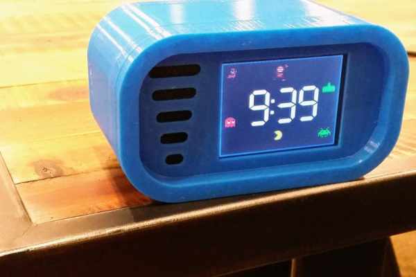
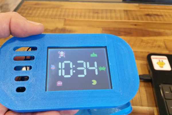
Build an interactive arcade bedside clock, with a touchscreen, and animated arcade figures that you can record a sound of your choice for the alarm.
This is an update of a previous project which now includes a 3D Printed Case and four separate programs to choose from
1. Arcade Clock – DK Mario, Space Invaders & Pacman animation
2. Pacman Clock – Interactive Animated Pacman game with clock functions
3. DK Clock – Interactive Animated DK game with clock functions
4. Tumble Ghost – Animated Pacman Ghost game based on Flappy Bird
Lots of fun to build and a great gift for anyone who likes to relive the nostalgia of 80s arcade game characters
** If you like this instructable please vote for it in the “Clocks Contest” by pushing the button at the bottom of the page ***
Many thanks !!
Step 1: Gather the Materials
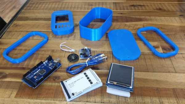
- Arduino Board – Arduino Mega 2560 (Items 1, 2 and 3 can be purchased as one bundled order)
- Touch Screen Arduino Shield – 3.2 inch Mega Touch LCD Expansion Board Shield
- Touch Screen – 3.2″ TFT LCD Display + Touch Screen for Arduino’s Mega 2560
- Real Time Clock module – DS3231 RTC
- Voice Recorder Module – ISD1820 Voice Recorder
- PLA Filament for 3D Printer
- Two Part Epoxy Resin for gluing case together
- USB Cable 2m length USB charger (used for the power supply for the clock)
- Hot glue gun
- Cable Ties X 3
Optional Auto Back Light Dimming Components only required if a Bedside Clock
- Resistor 270k Ohm
- Zener Diode 3.3v
- 0.5 watt Resistor 47 Ohm
- Light Dependent Resistor (LDR)
Step 2: Print the 3D Case
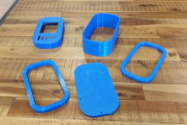
I printed the clock case on a Creality Ender 3. All of the 3D print files and instructions for the case can be found here on Thingiverse
Step 3: Build the Circuit
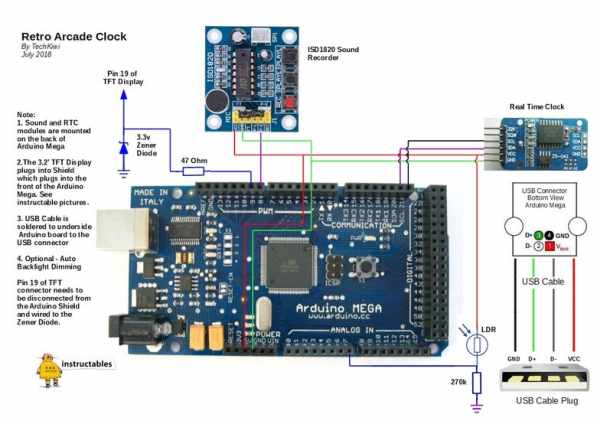
The overall circuit contains a Real Time Clock, Arduino Mega, Sound Module, Touch Screen and a Screen Sheild.
1. Real Time Clock
Mount the Realtime clock on the back of the Arduino Mega as in the picture provided. I used a hot glue gun and packing foam to ensure they are not touching and there is some cushioning to absorb movement. In my case, I soldered 2 of the RTC legs directly to the Arduino and used hookup wire to connect 5v and GND to the Arduino.
2. Sound Recording Module
These are really cool and easy to use. In a similar fashion as above, use foam and hot glue to position the module and the speaker on the back of the Arduino taking care to ensure they are insulated from touching. The Sound Module is triggered by D8 on the Arduino, so this and the power supply need connecting as per the circuit diagram provided.
3. Auto Backlight Dimmer (Optional)
If you intend on using as a bedside clock, then you will likely want to automatically dim the backlight at night so it doesn’t affect your sleep. (If not then you can skip this step!) Unfortunately, the backlight in the TFT screen is hard-wired into +3.3v and cannot be adjusted with the Arduino. This means we have to disconnect it and reconnect to a PWM pin on the Arduino to control the Backlight brightness. I wanted to do this with minimal damage to pins or tracks on the components so took the following approach. Follow the steps below carefully
(a) To achieve this a Light Dependent Resistor (LDR) is positioned at the back of the unit to detect the light. Drill two 3mm holes in the case and push the LDR legs through the holes. Use hot glue on the inside of the cabinet to hold the legs in place. Solder two wires on the inside of the case and connect them as per the circuit diagram. Add a 270k Ohm Resistor to A7 of the Arduino as per the circuit diagram.
(b) Remove the TFT Display, and place it on a firm surface. Identify pin 19 (LED_A) and carefully remove a few millimeters of the plastic at the base of the pin. Bend the pin flat and away from the connector as per the picture above. Check that the TFT Sheild can plug in snugly and that the bent pin does not obstruct the plug or socket.
(c) Solder a 47 Ohm register to the bent over the pin and connect a wire from the resistor to D9 of the Arduino Mega. The Arduino D9 pin can sink up to 40mA so the resistor limits this to less than this. Attach a 3.3v Zener Diode to the same pin (LED_A) and connect this to earth as per the diagram. The purpose of this is to protect the backlight from overvoltage as it will regulate the voltage to 3.3v.
4. TFT Screen and Arduino Shield
Carefully push the 3.2′ TFT Touch Screen connectors into the TFT Arduino Shield. Then carefully connect to the top of the Arduino as per the picture provided. The RTC has a battery so will retain the correct time even if power has been removed. The Alarm time is stored in Eeprom on the Arduino which means it will be retained if there is a power cut.
Step 4: Load the Code
The Project will require the following files and libraries to be loaded before it will compile and run. The code is unique and built around the capability of the libraries, the hardware, some custom graphics and other projects that I’ve borrowed from.
Please Note: Development of the code for this project has used IDE v1.06 and some of the required libraries are dated. This means some people are having issues with the new IDE version 1.6 and above when loading code. Therefore in the interests of simplicity, I recommend people use IDE v1.06 and have included the correct version library files in zip files at the bottom of step 4 of the instructable.
1. Arduino IDE
I have been using an earlier version of the Arduino IDE, therefore in the interests of simplicity, I recommend that you download Arduino IDE version 1.06 on your desktop machine before you install the code. You can get his version from here .
2. Libraries
These need to be downloaded and added to the IDE (Integrated Development Environment) that runs on your computer, used to write and upload computer code to the physical board.
- UTFT.h and URtouch.h located in zip file below
- Time.h located in zip file below
- DS1307RTC.h located in zip file below
- Wire.h and EEPROM.h are already included in IDE V1.06
Credit for UTFT.h and URtouch.h goes to Rinky-Dink Electronics I’ve included these zip files as it appears the source Website is down.
4. TFT Screen Variations
The vagueries of TFT screens and manufacturers have led to these notes.
(a) Sainsmart – If you have purchased a 3.2′ TFT screen that is branded Sainsmart on the back of the TFT device you will have found they have to modify libraries to resolve display issues. If you have purchased a Sainsmart TFT Display already there is a fix below
Edit the file “initlcd.h” and modify the following line from
LCD_Write_COM_DATA(0x01,0x2B3F);
to
LCD_Write_COM_DATA(0x01,0x3B3F);
You will need to restart the IDE and then reload the code to the Arduino.
(b.) TFT Controller Chipset – People who have purchased a 3.2″ TFT screen may find they could also have one of two different chipsets “SSD1289” or “ILI9341” The annoying thing is that it’s not easy to distinguish the difference online. The good news is that its easy to fix. If you get a blank screen after loading the code then it’s probably because it’s an ILI9341 controller.
To fix you need to make the following changes to the code. Edit the code and modify the following line of code
from
UTFT myGLCD(SSD1289,38,39,40,41); //Parameters should be adjusted to your Display/Schield model
to
UTFT myGLCD(ILI9341_16,38,39,40,41); //Parameters should be adjusted to your Display/Schield model
Now try reloading the code to the Arduino.
(c.) Inverted Touch Screen Controls
Some makers have reported that the Y axis touch screen buttons has been reversed. A fix for this was identified by @dissy where two lines of code to change to flip the touch screen reading.
Do a find for: “yT = myTouch.getY();” Change it to be: “yT = 240 – myTouch.getY();”
Don’t forget to search twice, the first instance is for controlling pacman in clock mode, the second is for in the setup menu.
5. Graphics Files
There are a group of bitmap files that I have included below that need to sit in the same subdirectory as the Arduino code when you begin to load into the Arduino. Therefore download the files below and use the IDE to load.
6. Setup the Clock
Once the code has loaded successfully press the center of the screen and this should bring up the setup screen. Use the menu to set the time and the alarm in 24-hour format. Press the SAVE button to store the setting. The RTC has a battery so will retain the correct time even if power has been removed. The Alarm time is stored in EEPROM which means it will be retained if there is a powercut.
7. Testing the Alarm
The Sound module is used to provide the Alarm. The ISD1820 is controlled by the Arduino D8 pin. Sound can be easily added by playing sound into the microphone while simultaneously pushing the record button on the ISD1820. In my case, I recorded the original Pac-Man introduction music from an audio file played through another device. Once the sound is recorded the recording can be tested by pushing the PLAY-E button which should play the sound through the speaker. Use the setup menu to set the clock time and the alarm time a few minutes apart. Be sure to “SET” the alarm and push the “SAVE” menu buttons. Once back to the main screen the Alarm should sound when the time occurs. Turning off the Alarm can be done by pressing the center of the touch screen panel resulting in the Setup Screen.
8. Touch Screen Calibration
Some makers have found that the Buttons on the Setup Screen do not align with the TFT touch controls. In these cases the Touch Screen needs calibration. This can be easily done by using the Touch Screen Calibration code and instructions provided in the URtouch library. Follow these instructions if you observe this issue.
9. Four Different Programs to choose from
1. Arcade Clock – DK Mario, Space Invaders & Pacman animation
2. Pacman Clock – Interactive Animated Pacman/Ms Pacman game with clock functions
3. DK Clock – Interactive Animated DK game with clock functions
4. Tumble Ghost – Animated Pacman Ghost game based on Flappy Bird
Source: Retro Arcade Clock – Arduino