Here I will show how I made a “Remote Social Touch” early prototype.
This was made for an explorative stage for my PhD, however, anyone can make their own and alter as they wish to generate their own final version.
“Remote Social Touch” (RST) basically is a way to send or receive physical touch massages from a remote person(s). For example, you can send a hug, a kiss, or just a simple touch.
This prototype has 2 pieces, the sender piece uses a touch sensing to sense the touch applied on it then send it wirelessly to the receiver piece, and a receiver piece that uses force feedback to render the touch received from the sender piece.
In this version of the prototype the communication is done directly between 2 ESP32 board wirelessly, however, people may alter the code to have it over the internet to be like a messenger for touch.
The cover and the outside material of this version are made of fabric as it was the easier and fastest way to get my hand on but feel free to be creative to use any other material.
The prototype is:
- Consists of two parts: the sender and the receiver.
- Wearable, so it is possible to test various locations on the body.
- The communication is done wirelessly.
- The communication is done in a live manner if one sends a message then the other person feels the message directly without any delay.
- The feedback can be coded by the users (a symbolic way of sending a message) which means that one may assign meaning to the feedback.
Step 1: Materials
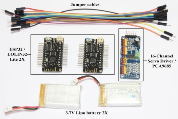
2 => ESP32 => It is an Arduino board that has wireless capability and has enough inputs.
1 => 16-Channel Servo Driver / PCA9685 => To manage and easily control the various servo motor used in this prototype.
9 => SG90 9G Servo Motor Mini => It is a 180-degree rotational motor, able for precise positioning based on the degree of rotation.
2 => 3.7V 1100mAH 1S Lipo battery => The prototype is using 3.7-4 volts for an energy source. Batteries will allow it to be portable however it can use USB cables to connected to another energy source with enough volts.
Jumper cables / various other cables => It is used to connect input and output.
Wearable Conductive Sewing Thread with Stainless Steel Support =>This is used to connect the conductive fabric to the cables or the Arduino board, it is not necessary it can be replaced with cables.
Woven Conductive Fabric => It is a fabric used to create the touch sensor by sensing the skin conductance.
2 => 2-Position Slide Switch => To switch the energy source on/off.
Fabric and sponge material for covering => can be replaced with whatever you like
Step 2: Putting All the Electronic Parts Together
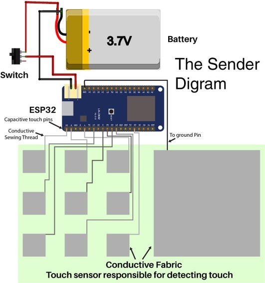
Fellow the diagram to put everything together.
- The sender part consists of the electronic board and the touch sensor. This part can be powered by a battery or a 3- to a 4-volt energy source. The touch sensor is made of two layers of conductive fabric with a separation layer, when the sensor is touched it allows the current to go through which will yield a successful touch indication.
- The receiver part consists of the electronic board and force feedback actuators. This part can be also powered by a battery or a 3- to a 4-volt energy source, however, it may need different power voltage and ampere depending on the motor actuator you use. The receiver part contains 9 servo motors that make the force feedback actuator. The actuator delivers the feedback based on rotation that feels like a light pressure on one’s skin. All 9 actuators are arranged in 9X9 grid format.
The communication is done in a live manner, as soon one touch the touch sensor the actuator moves.
Step 3: The Code
The codes a combination of other codes that made the whole needed codes.
Download the codes and uploaded them to each board depending on whether it is a receiver or sender.
Also, please install servo and ESPNow libraries
Next step I will explain the code.
Step 4: Code Explanation, the Sender
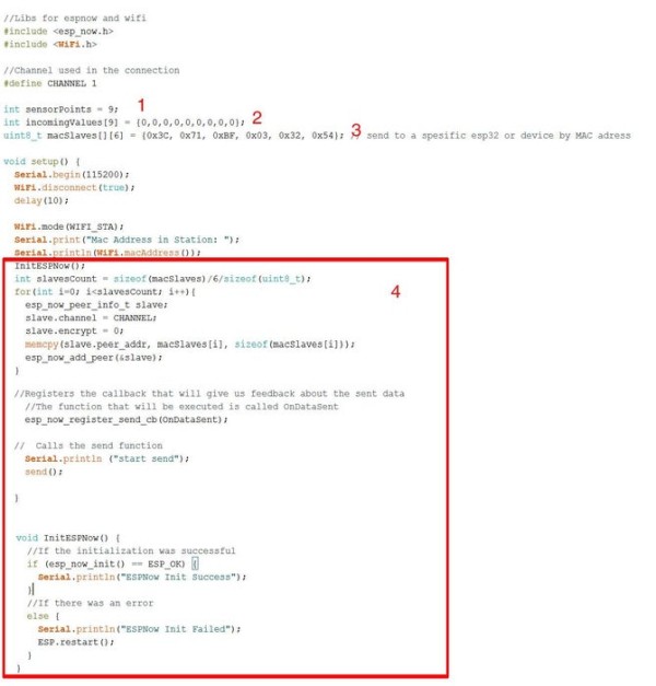
- The number of touch sensing points, here I have a 3×3 grid so the total is 9.
- The starting values are 0 => no data yet for each point.
- The MAC address for the receiver ESP32.
- This is the code for “ESPNow” which is the way the 2 boards are communicating over onboard WIFI.
- The number of touch sensing points, here I have a 3×3 grid so the total is 9.
- This is the number of raw used in point 8.
- The starting values are 0 => no data yet for each point, the word “values” is the value to be sent to the receiver, if you change the word you need to change it in point 10 and 12
- Here I am using arrays within an array to collect and detect the touch sensing.
- Here am adding the value of the touch sensing to each slot in the array, I am using onboard capacitive touch sensing, you could also use other ways but the code should be changed.
- This is for counting reading the touch then spitting out a value to send to the receiver which is whether a point is recording a successful touch or not, this is happening for each of the 9 points. You need to adjust this to add more or less depending on the raw count in number 6.
- The MAC address for the receiver ESP32.
- This is the value that will be sent to the receiver.
- This is the code for “ESPNow”.
Step 5: Code Explanation, the Receiver

- This is information for the servo driver you need to experiment with the number to have the right rotation degree.
- The incoming array slots numbers = to number of touch sensor = to the servo motor number
- This to increment increase the servo position if the touch still = 1, the person still touching the sensor
- The minimum degree to rotate the servo
- The maximum degree to rotate the servo
- This number is equal to the number of servos and the touch sensor correspond to each servo
- This is the pin number to connect the servo driver sda and scl, maybe it is different for you
- This is for ESPNow communication
- This is for the servo driver
- Here resetting the position for all the servo motor to 0
- This is for ESPNow communication
- This is for ESPNow communication, the word “data” is the values coming from the sender if it is changed then change it in point 13
- Here checking the data for each touch sensor and it corresponds to servo motor, if it is touching then keep the motor rotate until it reaches its max value.
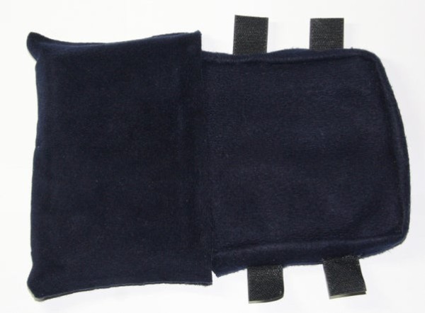
Step 6: The Sender, the Outer Layers and Shell
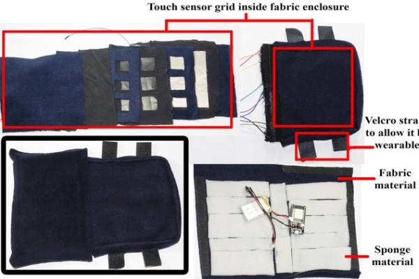
You can use any material to make the cover.
- The first layer is only fabric.
- The second layer I am using fabric too, I glued on to it 9 squares of conductive fabric then each one is connected to a jumper cable.
- Then I added a few filling fabric with 9 holes to have space between the first layer and the last layer.
- The last layer has a big square conductive fabric that is connected to the ground jumper to the board.
- I am also casing the board and the battery in fabric and sponge but you can find other ways.
Step 7:
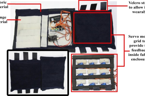
For the receiver, you can use any material to make the cover.
The whole thing is encapsulated in a fabric case.
Using think rubber to create a frame that can glue the servo motors onto it.
The electronic parts are also cased in fabric and sponge.
The servo motor head has a sponge piece attached to it to create a light pressure on human skin when it turns.
Step 8: Finally
This prototype can be further enhanced by making 2 pairs that work over the internet then you can send one to your loved ones while you are not able to touch them. This will help you stay in touch “physically” with your loved one. Be creative, make any kind of feedback you like and as much you want. Have fun.
Source: Remote Social Touch