Summary of Portable Portrait Painter
This portable portrait painter is a unique Arduino-based plotting machine featuring an integrated camera and screen, allowing it to operate independently without a computer. It captures images and paints watercolor portraits in under five minutes. The project requires skills in 3D printing, Arduino coding, soldering, and assembly, with an estimated build time of 20+ hours and significant material costs.
Parts used in the Portable Portrait Painter:
- MGN9 linear rails
- Stepper motors
- Toothed drive pulleys
- Smooth idler pulleys
- Y-carriage top and LHS/RHS parts
- Y-carriage spacers
- Harwin spacers
- 3mm plywood baseplate
- Laser cut reinforcing offcuts
- M3 bolts and square nuts
- 2020 extrusion lengths
- Metal T nuts
- Rubber vibration washers
- Cork vibration dampeners
- Mini clothes pegs (for springs)
- Wood-filled PLA filament
- Push buttons (calibrate, paint/stop, camera)
- X-axis carriage
- Servo bracket
- Limit switches
- Ø5mm magnets
- Spiral USB cable
- Presser foot and handle
- Compression spring
- Super glue
Introduction
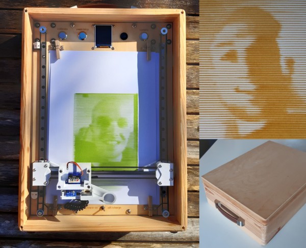
There are probably over one-hundred Arduino based plotting machines on the internet with instructions available on how to make them. What makes this one unique (as far as I know), is the inbuilt camera and screen. Other plotters must be connected to a computer. This one works completely independently.
The 20fps video shown on the screen makes it easy to capture pictures with the camera, then just press the paint button to have a watercolour portrait in less than 5 minutes.
Thanks to Indrek Luuk who wrote the camera/video code and to Sourav S who solved how to read information from the screen (written permissions obtained for contest entry). Thanks also to Darcy Whyte (InventorArtist) who inspired the brush-pen approach to the plotter.
Guide to the instructions
The following instructions are a detailed step-by-step guide to making your own portable portrait painter. Before attempting this project you should have the following skills:
- Operate a 3D printer
- Able to upload sketches to an Arduino
- Soldering
- Assembly of parts
- If you want to adjust the design, you’ll need to be able to write code for Arduino and adjust Fusion 360 CAD files.
The project is not a small undertaking:
- The total parts cost (excluding 48x 3D printed parts) is almost £400!
- The total cost of tools needed is £371 (including tools you may already own e.g. a £180 3D printer).
- I estimate that it will take 20+ hours to complete the project.
Step 1: Tools and Materials
Attached are 3x lists:
- A list of all tools required.
- A list of all parts, fasteners, and electrical components required.
- A list of all the parts you need to print.
- I’ll refer to the 3D parts by name in the instructions. You’ll know I’m referring to a 3D printed part because it will be in bold, and then you can check this list (alphabetical order).
If you want to buy everything before getting started, you’ll need to skip ahead to the steps for procuring the laser cut baseplate, and for making the PCB.
Also attached are all the STL files for printing.
Step 2: Overview of the Design
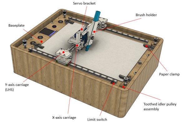
Once built, the machine should look like the Fusion 360 CAD image above. Key parts are labelled for reference.
Here is a public link which should let you view the Fusion 360 design: https://a360.co/39e3x8v
Unfortunately you cannot download from this link (that would require me to have a paid F360 subscription), but you can take measurements and reverse engineer if you want to modify the design.
Step 3: Procure the Laser Cut Baseplate
You could make the baseplate using hand tools. The 3mm plywood could be sawed to size, and the various holes drilled using a hand drill. The screen hole could be cut using a fret saw and file.
However, a laser cut baseplate will give you the benefits of:
- Much cleaner holes for the camera & screen.
- Ensures that the holes for mounting the linear guides will be accurate enough.
- Laser engraved text!
I chose one of the many people offering a laser cutting service on eBay, and sent them the DXF file. Most of them will be happy to work from the DXF but make adjustments to the final part.
Make sure to keep the two parts that are cut from the spare material where the screen is mounted. These ‘offcuts’ are used to reinforce the toothed idler pulley assembly.
Adjust the DXF file
The laser cutting service will be able to make edits to your
DXF file. Edits you need to make are:
- Measure the internal dimensions of the box you have purchased (or built) and ensure that the baseplate is going to fit inside. Beware that the box walls might not be straight – the opening could be narrower at one end, or in the middle. You can tell the laser cutting service to adjust the overall L x W dimensions according to your measurement.
- There is placeholder text in the DXF, you might want to replace this text with a font of your own choosing – just ask the laser cutting service.
- If you have purchased a different 1.8” screen, you must measure and adjust the mounting holes accordingly.
- You could get creative and add your own text or images to be engraved.
Clean up the sooty residue
The laser cut part will almost certainly arrive with sooty residue still on it. This can be easily cleaned off by scrubbing it with a wet soapy toothbrush.
Apply a spray-on lacquer
Use a can of spray-on lacquer (I chose matte finish) and apply 3 layers to the baseplate, sanding in-between layers. Watch some YouTube videos on the correct technique for this. The spray-on lacquer will protect the wood, especially from the brush-pens. Once the lacquer is applied if you accidentally paint the wood with the brush pens, you can wipe it off with a damp cloth.
Step 4: Make the H-bot Gantry
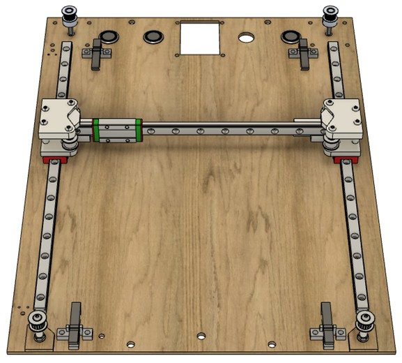
Once this step is complete, your assembly should look like the picture above.
Prepare the MGN9 rail:
You might think that using MGN9 bearings is an unnecessarily expensive option for this low-precision painting machine. I chose this rail for 2 reasons: Firstly, the small size of the rail and carriages. Secondly, the rail is performing a dual purpose – it is clamped down onto the front of the plywood and forcing the plywood to be straight and flat.
Cut the MGN9 rail for the X-axis
Assuming that you ordered the MGN9 rail in 3x 300mm lengths,
you will need to cut the X-axis to length. The X-axis needs to be cut to 220mm length (11 holes will be available along its length). A hacksaw is not the best tool for cutting this hardened steel, but it is the cheapest. Follow these instructions to make it as painless as possible:
Cutting the MGN9 rail with a junior hacksaw will take 20 minutes.
- Each 150mm junior hacksaw blade will only cut about 1mm depth before the blade is blunt. Once the blade is blunt, you could saw for 24 hours and make no further progress.
- It only takes 2-3 minutes for the blade to be blunt.
Therefore the way to do it is:
- Get a pack of 10 hacksaw blades (about £2).
- Saw for just 3 minutes before swapping to a new blade. (It will take 6-7 blades in total).
The MGN9 cutting guide will help to align the blade as you start cutting, and if the blade jumps out while cutting then the plastic will protect the rail from getting scratched. Fasten the 3D printed cutting guide to the rail using M3 nuts and bolts.
Lubricate the ball bearing races
Things to know about linear recirculating bearings:
- For whatever reason, bearing manufacturers supply their bearings unlubricated. Due to the close tolerances they will not run smoothly and freely.
- MGN9 bearings are a knock-off design of much more expensive & professional Hiwin bearings. The ones I received were quite crunchy, and would always stick at specific positions, indicating relatively poor manufacture.
You will find YouTube videos that go into detail about cleaning and then greasing these bearings. They involve extracting all the balls from the carriages and it looks difficult and time consuming. Instead, I just added lots of grease to the carriages until they ran nicely (avoiding disassembly). I will describe the approach I used.
The grease I recommend is SuperLube. It’s a widely available grease. SuperLube is non-toxic and you can dispose of any greasy paper-towels into your normal household waste. I was able to buy a convenient 10ml syringe-full (rather than a full tube). You’ll only need a fraction of a millilitre.
I dispensed the SuperLube directly onto the exposed ball-bearings using a 23G needle. Do not be tempted by the holes in the MGN9 carriages which look like they are designed to accept grease – these are grease holes in the official Hiwin carriages but they don’t go anywhere in the MGN9 carriages.
Cut the needle short to reduce the force needed to dispense the grease. You will need to use pliers to shape the end of the needle a little so that it fits into the ball-bearing races. Then insert the needle amongst the ball bearings and squeeze the syringe hard to dispense grease.
I found dispensing the grease quite difficult due to the force required. A smaller syringe might have helped, or an alternative approach might be to apply grease directly to the linear rail and run the carriage over it, cleaning up the mess afterwards with a paper towel (not tested this).
Continue to apply grease until the carriages move smoothly.
Assemble & mount the Y-axis carriages
Assemble the Y-axis carriages onto the MGN9 carriages according to the exploded diagram.
For each of the two carriages, you will need:
- (2x) M3x30
- (2x) M3x25
- (2x) M3x8
- (2x) M3 square nuts
- (4x) 3mm Harwin spacers
- (2x) smooth idler pulleys
- (1x) Y-carriage top
- (1x) Y-carriage LHS/RHS
- (2x) Y-carriage spacer
Mount the MGN9 rails
It is important that the Y-axis MGN9 rails are mounted parallel to each other for the gantry to move properly. To achieve this:
- Mount the 3 linear rails into position, doing up the fasteners so that they are snug but not tight and allow some movement of the rails.
- The X-axis is secured in place using 4x M3x8mm bolts and square nuts through the Y-carriage LHS/RHS mounting holes. Underneath the head of each bolt is a 1mm MGN spacer which will stop the end of the bolt protruding too far and hitting the belt.
- The Y-axes are secured in place using the 2x 2020 extrusion lengths, 4x M3 x 8mm bolts, and the 4x metal T nuts. Due to the importance of accurately mounting the axes, I don’t recommend using 3D printed T-nuts (which are used elsewhere in the design). The 2020 extrusion should be perpendicular to the Y-axes.
- Tighten up the X-axis bolts.
- Tighten up 2x bolts on one of the Y-axis rails.
- Move the gantry to the very top of the Y-axis and tighten the top bolt.
- Then move the gantry to the very bottom of the Y-axis and tighten the bottom bolt.
- Check if the gantry can move freely back to the top of the Y-axis , now that all the bolts have been tightened. If not, loosen the top bolt to allow the rail to pivot, move the gantry to the top, and re-secure the bolt.
- Repeat the process of moving the gantry up and down while tightening and loosening bolts until the gantry can move freely.
Mount the stepper motors
Mount the two stepper motors to the baseplate using 8x M3x10mm bolts, 8x rubber vibration washers, and 2x cork vibration dampeners. The vibration dampening cork & rubber washers will help reduce the noise of the machine.
Mount the toothed drive pulleys to the stepper motor shafts using the grub-screws. You will need to adjust the height of these pulleys later so that they are at the same height as the other pulleys.
Mount the idler pulley assemblies
Assemble the two toothed idler pulleys to the baseplate according to the exploded diagram. The 3mm plywood parts are used to spread the forces caused when the belt is under tension.
For each of the two toothed idler pulleys, you will need:
- (1x) M3x40mm socket button head screw
- (1x) toothed idler pulley
- (1x) Harwin spacer
- (1x) Idler pulley spacer
- (2x) M3 flange nuts
- (1x) Reinforcing plywood laser cut offcut
Assemble and mount the paper clamps
Disassemble the mini clothes pegs to get their springs, then use the springs to assemble the paper clamps according to the picture below. Unless you manage to buy mini clothes pegs with the same sized springs as mine, you will need to edit the design of the paper clamps in Fusion 360, or another CAD software.
I printed the paper clamps using wood-filled PLA filament, which improves the aesthetic and gives a nice tactile feel.
Mount the paper clamps using (8x) M3x12mm bolts & (8x) M3 hex nuts.
Install the 3x push buttons into the holes marked ‘calibrate’, ‘paint / stop’, and ‘camera’.
The H-bot gantry assembly is now complete.
Step 5: Make the Brush Holder Assembly
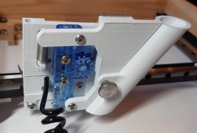
Probably 80% of the time spent designing the machine was on this brush holder assembly. It’s densely packed with components and should be fun to put together.
Once the next steps are complete the assembly should look like the front/back pictures above.
Next steps:
- Step 6: Assemble the X-axis carriage
- Step 7: Assemble the servo bracket
- Step 8: Assemble the brush holder
Step 6: Assemble the X-axis Carriage

This step refers to the 3D printed part ‘X-axis carriage’.
You will need:
- (2x) M3 x 8mm socket button head screws.
- (4x) M3 x 12mm socket button head screws.
- (4x) M1.2 x 12mm slotted screws
- (4x) M1.2 nuts
- (4x) Ø5mm x 10mm magnets
- (2x) M3 threaded insert, 4mm length, Ø4.3mm OD
- (1x) M3 threaded insert, 5.2mm length, Ø4.3mm OD
Install the threaded inserts
There are several ways you can install threaded inserts. My
personal preference is to press them into an undersized 3D printed hole with a vice.
- It is strong enough that the thread won’t come out unless the force is high enough to destroy the 3D printed component anyway.
- It doesn’t require any tools beyond the vice.
- If you scrap the part and want to retrieve the threaded insert, you can just crush/lever it out of the plastic with the vice with ease. I expect it’s not worth the trouble for an insert which has been melted or glued into place.
Install the M3 threaded inserts to the X-axis carriage. I recommend putting a long M3 bolt into the threaded insert when pressing the insert into place to give better access for the clamp as shown in the picture above. I used the shorter threaded inserts for the two holes next to the belt clamp.
Mount the limit switches and magnets
Mount the limit switches using the M1.2 x 12mm bolts and M1.2 hex nuts according to the exploded diagram.
Mount the magnets into the X-axis carriage using super glue to hold them in place. The North/South orientation of the magnets is important – the X-axis carriage must magnetically attract the servo bracket. Skip ahead in the instructions to and glue the magnets into the servo bracket – the orientation of magnets in the servo bracket is not important.
Place a magnet on the outside of the servo bracket to find the correct orientation for the magnet. Then, glue the magnet into the X-axis carriage making sure the orientation is correct. Repeat this for the 4x magnet installation locations on the X-axis carriage, so that the servo bracket snaps into place whether in the horizontal or vertical mounting position.
Strip and insert the spiral cable
The spiral USB cable should have a short straight section at the end where it connects to the USB connector. Snip off the USB connector, and then strip approximately 20mm of the outer black insulation to expose 4x wires. Strip the end of each of these 4 wires (e.g. 3-5mm).
Once stripped, force the spiral cable into the front of the X-axis carriage so that the outer insulation just protrudes from the exit hole. This should be a snug fit, as the hole should be providing strain relief to the cable (prevent it from accidentally coming out). If the fit is loose, consider using some glue.
Install the presser foot
The presser foot gently pushes down the paper or card while the machine is painting. Paper is wavier than I thought, and so the presser foot is essential. To install the presser foot you will need:
- (1x) M4x8mm socket button head screw
- Presser foot
- Presser foot handle
- Ø5.6 x 17.5mm compression spring from Amtech AM-S6210 assorted springs
The M4 button head screw provides a smooth surface to run over the paper without gripping it. Use an M4 tap to thread the internal hole in the presser foot, then install the M4x8mm screw.
Remove any excess plastic from the presser foot and presser foot handle so that they can move smoothly within the presser foot hole in the X-axis carriage.
Insert the compression spring into the hole. Insert the presser foot after the spring. Apply a blob of super glue to the end of the presser foot handle and insert through the top of the X-axis carriage into the presser foot handle.
Source: Portable Portrait Painter
- What makes this plotter unique compared to others?
This plotter features an inbuilt camera and screen, allowing it to work completely independently without needing a connection to a computer. - How long does it take to complete the project?
The author estimates that it will take more than 20 hours to complete the project. - Can I modify the design if I want to adjust it?
Yes, but you must be able to write code for Arduino and adjust Fusion 360 CAD files. - Why did the author choose MGN9 bearings for this machine?
The author chose them for their small size and because the rail clamps down onto the front of the plywood to force it to be straight and flat. - How should I clean the sooty residue from the laser-cut baseplate?
You can easily clean the sooty residue by scrubbing the part with a wet soapy toothbrush. - What type of grease is recommended for the MGN9 bearings?
SuperLube is recommended as it is widely available, non-toxic, and safe for household disposal. - How do I ensure the Y-axis rails are mounted correctly?
You must mount the rails parallel to each other, tightening bolts incrementally while moving the gantry up and down to check for free movement. - What filament is suggested for printing the paper clamps?
Wood-filled PLA filament is suggested to improve the aesthetic and provide a nice tactile feel. - Is the presser foot essential for the painting process?
Yes, the presser foot is essential because paper is wavier than expected, and the foot gently pushes down the paper while painting. - What tools are required before starting this project?
You need to be able to operate a 3D printer, upload sketches to an Arduino, solder, and assemble parts.