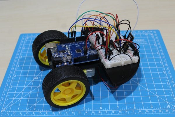
A great introductory project for those diving into the IoT and Arduino platform. Working with motors and an IR sensor helps newbies understand various components and sensors compatible with the Arduino. Using the remote control, you will be able to control the robot’s movement allowing the robot to move in straight lines or turn based on human input.
Created by Divyank Shah, an upcoming Computer Science major at the University of California, Riverside. Divyank Shah is an ambitious individual looking to study further in computer science with a deep interest in microcontroller and microprocessing technologies.
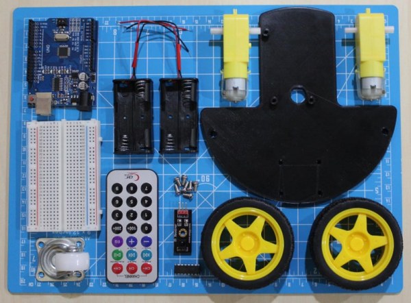
Supplies
- Arduino Uno
- 400 Point Solderless Breadboard
- Caster Wheel (Universal Wheel)
- 2 x TT Motors (1:48 Gearbox)
- 2 x TT Motor Wheels with Slotted Inserts
- 2 x 2 AA Cell Battery Holder
- 4 x AA 1.5 V Batteries
- L293D Motor Driver
- IR Sensor with Remote
- Assortment of Jumper Cables
- Double Sided 3M Tape
- Soldering Iron with Solder
- Heat Shrink / Electrical Tape
- Screw Driver
- 3D Printer (Ender 3 V2 used)
Step 1: CAD: Designing the Base

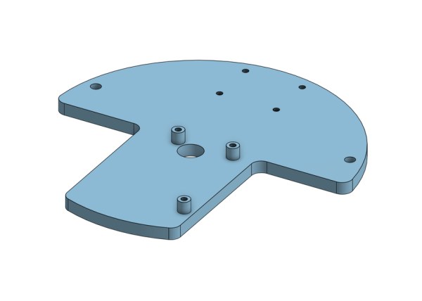
When designing the base, there are a few points to consider. One of the main challenges is spacing and ensuring everything is able to fit including wires. Common designs including starting with a circle or square and developing a base that accommodates your needs.
Starting with a circle extruded 6 mm, I first accommodated for the wheels. With a 66 mm diameter and a tire width of 26 mm, I was able to remove a significant portion of the circle to ensure the wheels had enough room to move around and would not get caught upon other electronics or parts of the base.
On the other side of the circle (the underside), the holes for mounting the caster wheel were made. The caster wheel used had dimensions of 33mm x 27mm. These holes are unique in the sene that they are threaded holes which the screws perfectly fit into. Using this excellent guide by John Titterton, Given that I was using M3 standard screws, I was able to create holes 3 mm wide and adopt the concept and create the helix with a 0.5 mm pitch that ran clockwise. As per the equilateral triangle, the side length was 0.45 mm and I performed sweep on the path of the helix. Repeating this process 4 times, I was able to create my caster wheel mount.
The same concept was applied for the mounting holes of the Arduino. However, this time, standoff-like cylinders were created to allow the Arduino to sit comfortably as the soldered joints on the bottom of the Arduino would prevent a flush mount. An excellent reference image depicts the various holes on the Arduino and their dimensions.
Lastly, 3 holes were created and spread throughout the base to allow or convenient cable management. Given the battery’s position on the bottom, two holes on either ends will allow the battery terminals to be connected to the breadboard and Arduino. These holes were dimensioned at 5 mm to allow a wire to comfortably it through. The hole near the center is to allow wires coming from the motors to be connected to the L293D motor driver. The hole was dimensioned at 12 mm to allow at least 4 wires to fit through comfortably. I finally used a 5 mm filet on the sharp corners to smooth out any rough edges.
Step 2: Assembly: Putting Everything Together

Using 4 x M3-6 screws, we can first attach the caster wheel. When attaching the wheel, we need to ensure that the wheel is facing the opposite direction of the makeshift standoffs we created for the Arduino.
If the TT motors do not have wires already soldered onto the leads, then solder the wires prior to fixing them to the base. We will be placing the motors on the “stem” of the mushroom shape. Preferably, the leads of the motor should be facing inward to avoid interference with the wheels, we have placed the red terminals closer to the base as this will make our coding more consistent later on. You may choose to change up the configuration, however, be aware that changes in code will need to reflect accordingly. Using 3mm tape we can attach the motor to its position. Ensure to place both motors prior to prevent the motors from not having enough space and interfering with one another. We can now attach the wheels on the ends of the TT motors and thread the wires through the 12 mm hole near the center.
Moving onto the batter holders, we first need to attach them in a series configuration before fixing them to the base. Attach one of the positive terminals (usually red) to a negative terminal of the other battery holder (usually black). Solder the wires together and use heat shrink or electrical tape to conceal the solder joint. The final product should result in a single positive terminal (usually red) and a negative terminal (usually black) sticking out on either sides of the battery holders. We can thread these wires through the 5 mm holes created and fix the battery holders using 3 mm tape (it is recommended you attach the tape beforehand as it may make soldering much easier).
Once complete, we can flip the base over to reveal the top where our makeshift standoffs should be. We can first screw the Arduino using the 3 threaded holes we have created. Lastly, we can attach the breadboard to the “head” of the mushroom. Many breadboards have a layer that can be peeled to reveal an adhesive, if not present, you may use 3 mm tape to attach the breadboard to the base.
Step 3: Wiring: Connecting Everything Together

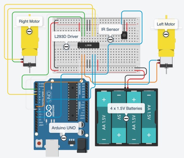
Using the diagram above, we can wire everything together. The batteries will first be wired to the positive and negative terminals of the breadboard. Ensure to power rails on both sides of the breadboard as we will be using these for the IR sensor and the motor driver.
We can now wire the motors next. Identify the left and right motor wires and attach them to the L293D motor. A close up has been provided to further understand where each wire is coming from. Ensure that you connect the correct wires together, otherwise issues may occur later on.
With the motor wires connected, we can connect the L293D to the Arduino. Using the diagram provided, connect the appropriate wires. Take your time to recheck your wires, as many mistakes usually occur while wiring the L293D driver.
We can then connect the IR Sensor to the power rails and Arduino. IR sensors from various brands may have a different wiring configuration/order, please check the data sheet to ensure your wiring is appropriate for your sensor.
Lastly, we can wire the VIN and GND ports to the power rails of the breadboard, to allow the Arduino to get power from the 4 x 1.5V batteries as we would like to be able to remotely control our robot. A wire from VIN will be connected to the positive terminal and GND will be connected to the negative power rail.
Step 4: Software: Test Program
With the wiring done, we can ensure that everything is working as intended. Below I have provided a test program, that will move the robot forward, backward, turn left, and turn right with 3 second intervals between each movement. Using this test, we can determine if we have wired anything incorrectly. For example, if we notice the robot moving backward when “Moving Forward…” we can deduce that our motors are reversed and the wiring can be changed to reflect so accordingly.
During this time, using the helper functions provided within the code, we can tell our robot to move in preplanned routes with the aid of time intervals.
Step 5: Software: Remote Control Operation
Once the motors have been tested and everything has been properly assembled. We first need to install the IRremote.h library. This will allow us to directly interface with the IR remote and IR sensor, allowing us to read and interpret values from the IR remote. To install the library we need to navigate to
Sketch -> Include Library -> Manage Libraries
This should bring us to a searchable database of various libraries we can install. We can type in “IRremote” and install the correct one, it is important the library name matches exactly as various other libraries yet may have different syntax which may result in further errors.
Once installed, we can upload the ArduinoCar.ino file to the Arduino to let it operate remotely using a remote control. The code uses values that are common with most IR remotes. However, if the car does not behave as expected please modify the IR values within the code to reflect the values of your remote control.
The code provided improves upon the ARDUINO CAR TEST PROGRAM from the earlier steps and includes various IR functions to add the remote operation functionality. Once it detects a signal has been received from the IR remote, the value is stored and matched with pre-existing values to map to certain behaviors. Based on the mapped behavior, it will move the motors in the appropriate manner. If the value “16736925” is received, then it will search the pre-existing values and notice that “16736925” is mapped with moving the car forward, hence it will call upon the moveForward() function created in the ARDUINO CAR TEST PROGRAM. When testing, ensure to plug in the wires from the batteries into the breadboard to ensure the Arduino and motors are receiving power.
Once everything is functional and the buttons are mapped correctly, we can enjoy our Arduino Remote Control car.
FURTHER IMPROVEMENTS:
If you would like to further improve your Arduino Remote Control Car, I would recommend, by having a dual battery system. A 9V for the motors, and 6V for the Arduino, this way, the motors have more juice and the car is able to have more operational time before the batteries need to switched. Additionally, more sensors can be added such as an ultrasonic to provide information such as distance from the closest object.
Source: Remote Control Arduino Car
