
Summary of Arduino Waveform Generator Shield
This article details the assembly of an Arduino Waveform Generator Shield Kit, a tool for testing and debugging electronic circuits. It generates four waveforms (sine, triangle, pulse, saw) ranging from 1Hz to 50kHz, controlled by three potentiometers for frequency, pulse width, and amplitude. The project utilizes specific components like an LM386 op amp, various resistors, capacitors, LEDs, and tactile switches mounted on a custom PCB.
Parts used in the Arduino Waveform Generator Shield:
- Momentary push buttons (x4)
- Linear taper 10kOhm potentiometer (x3)
- 0.25" knobs (x3)
- White LED (x4)
- 220Ohm 1/4Watt resistors (x4)
- Female header sockets
- Male header pins (x4)
- LM386 op amp
- 8 pin socket
- 10kOhm 1/4Watt resistor (x11)
- 20kOhm 1/4Watt resistor (x10)
- 220uF capacitor (x2)
- 2.2kOhm 1/4Watt resistor
- Arduino Uno or Duemilanove with ATMEL328P
- Shield PCB
- Battery snap
- 9V battery
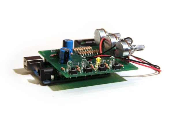
Waveform generators (also called function generators) are useful for testing and debugging circuits. They can be used to test the frequency response of electronic components like op amps and sensors or to characterize and troubleshoot audio effects boxes and pedals. This waveform generator shield is powered by an Arduino. It outputs four waveforms: sine, triangle, pulse, and saw, each waveform ranges in frequency from 1Hz-50 kHz. The frequency, pulse width, and overall amplitude (gain) of the waveforms is controlled by three potentiometers. Four indicator LEDs let you know which type of wave is currently being sent to the output. This Instructable describes how to put together the Arduino Waveform Generator Shield Kit I designed, if you’re interested you can also check out my original post about the Arduino Waveform Generator.
Additional Materials:
battery snap Jameco 109154
9V battery Jameco 198731
9V battery and battery snap or other power supply
This Instructable will show you how to put the Waveform Generator Shield together, if you want a more detailed description of the circuit check out my Arduino Waveform Generator Instructable.
 waveform generator.sch100 KB
Step 1: Header Pins
Solder two groups of 8 and two groups of 6 header pins to the PCB. Make sure to solder the header pins to the bottom of the board (the side that does not have any words). Here are some tips to keep the pins straight while soldering them down. The shield should fit nicely on an Arduino.
Step 2: Tact Switches
Press fit four tact buttons onto the side of the PCB, solder all four leads to the pads of the PCB.
Step 3: 8 Pin Socket
Solder one 8 pin socket to the part of the PCB labelled U2. Here are some tips for soldering the socket on straight.
(x4) momentary push buttons Jameco 119011
(x3) linear taper 10kOhm potentiometer Jameco 286273
(x3) 0.25″ knobs Jameco 136241
(x4) white LED Jameco 334502
(x4) 220Ohm 1/4Watt resistors Jameco 2157183
(x1) female header sockets Jameco 70755
(x4) male header pins Jameco 103393
(x1) LM386 op amp Jameco 24133
(x1) 8 pin socket Jameco 51626
(x11) 10kOhm 1/4Watt resistor Jameco 2157167
(x10) 20kOhm 1/4Watt resistor Jameco 691171
(x2) 220uF capcitor Jameco 606820
(x1) 2.2kOhm 1/4Watt resistor Jameco 2160981
(1x) Arduino Uno (Duemilanove is fine, but make sure it is ATMEL328P) Jameco 2151486
(1x) Shield PCB (Buy the shield and all the components here)
For more detail: Arduino Waveform Generator Shield
-
What waveforms does this generator produce?
The shield outputs four waveforms: sine, triangle, pulse, and saw. -
How is the frequency range defined?
Each waveform ranges in frequency from 1Hz to 50 kHz. -
How are frequency, pulse width, and amplitude controlled?
These parameters are controlled by three potentiometers. -
How do I know which waveform is currently active?
Four indicator LEDs show which type of wave is being sent to the output. -
Can I use a Duemilanove instead of an Uno?
Yes, a Duemilanove is fine provided it uses the ATMEL328P chip. -
Where should the header pins be soldered?
Header pins must be soldered to the bottom of the board, the side without words. -
How are the tact switches installed?
Press fit four tact buttons onto the side of the PCB and solder all four leads to the pads. -
What powers this device?
The shield is powered by an Arduino, typically using a 9V battery and battery snap.
