If you’ve even seen a fake candle you have probably noticed how it doesn’t look realistic. Whether you’re trying to add some atmosphere to a dinner or light up a jack’o-lantern, your choices are limited. A real candle has a fire hazard, but a fake candle will look tacky. If only there were a safe solution that didn’t look so bad. Enter Arduino.
Making a realistic candle may seem very difficult. For example, what does a real candle actually look like? How does an Arduino match the flickering pattern? Should the LEDs match each other? However hard it may seem, a step by step process can make any electronics problem simple.
For this project we will build a realistic and safe candle alternative with an Arduino and some LEDs. For this project you will need:
- 1x Arduino (or similar microcontroller)
- 1x Breadboard
- 1x 50 Ohm resistor
- 2x Red LED
- 2x Yellow LED
These parts are just suggestions, so you can use a different amount of LEDs or use a different resistor if you know what you are doing.
Step 1: Analyse Candle
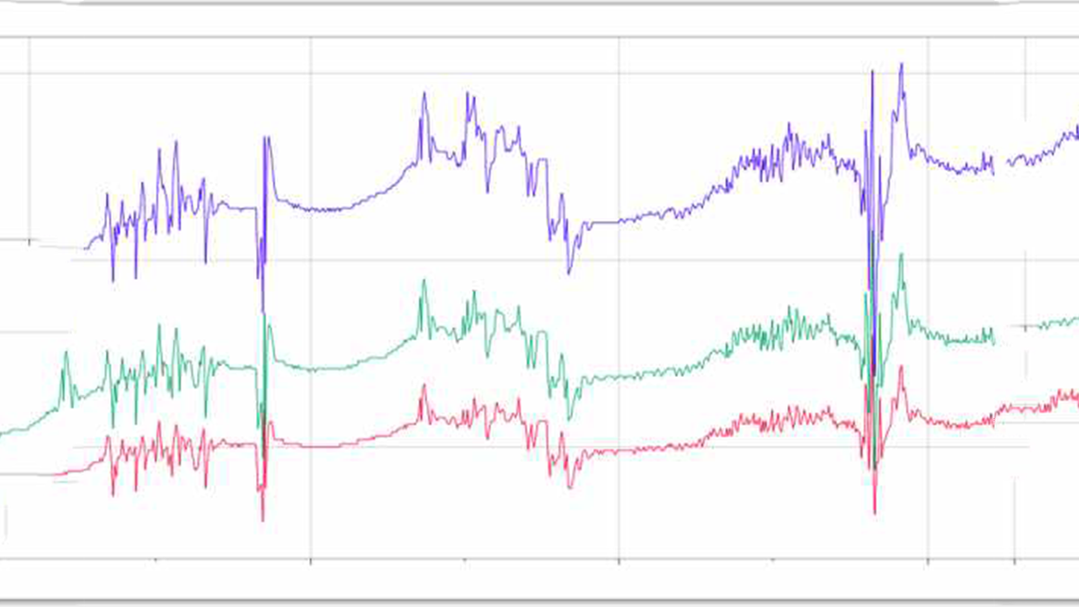
The first step to making a realistic candle out of LEDs is knowing what a real candle looks like. There are many approaches to this problem, and some are better than others. We could watch a candle and try to identify the flickering patterns in real time, but it is much easier if we instead use technology to help us. I used a camera connected to software that created a graph of the light levels.
First, the amount candle flickers is not always the same. While the frequency stays constant, the amplitude changes. Second, if you look at the general pattern you will see that you can split the flickering into different sections. Each section is between about one and five seconds long. Last, the candle seems to follow a general upward or downward curve in each section.
Now that we know how a candle flame should look we can start to build.
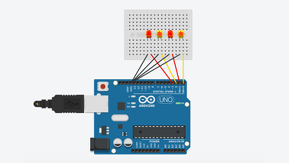
Step 2: Wiring
The simplest way to connect an LED to an Arduino is with a direct connection, however this poses some problems. LEDs can only handle a certain amperage, normally 20 mA; Arduinos will output around 55 milliamps.
To counter this problem, each LED should have a resistor blocking some of the current. The logical conclusion is to send every output through a resistor. While this works, it takes a lot of resistors to make this work.
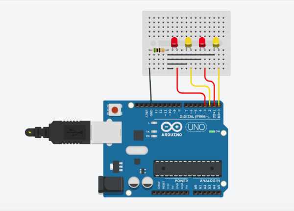
The best way to wire the LEDs is to send the ground through a resistor, thereby allowing every LED to share the same resistor while also keeping the output lines separate.
When you display this, you will want to make sure that the LEDs are unobstructed and look good. To do this it is good to use short wires and put each color every other.
Step 3: Code
I am assuming a basic knowledge of Arduino programming in this tutorial, so I will skip some parts of the coding process. Even if you do not know how to code, the Candle.ino file will work just fine and is thoroughly commented.
Now that we have our LEDs connected, we can code our Arduino to match the candle. As you may remember, our analysis of the candle told us that our LEDs should:
- change patterns every 1-5 seconds
- not always have the same amount of flickering
- have a constant average change in each section
The first step is to allow than candle to change patterns. It is easiest to do this with a for loop. Each run of the loop will be a frame, and the number of times it will loop controls the length of each section. Every time the loop finishes, a new loop will start. The pseudocode will look like this:
loop (forever) {
	loop (section length) number of times {
		flicker LEDs
		wait (frame length)
	}
}
For the flickering amount, we should assign maximum and minimum values to two variables and pick a random value in between them. This will allow us to both change the average brightness and the range in flickering for each LED. During every section the parameters will be changed. Our new pseudocode:
loop (forever) {
	set LED range
	loop (section length) number of times {
		flicker LEDs with range as parameters
		wait (frame length)
	}
}
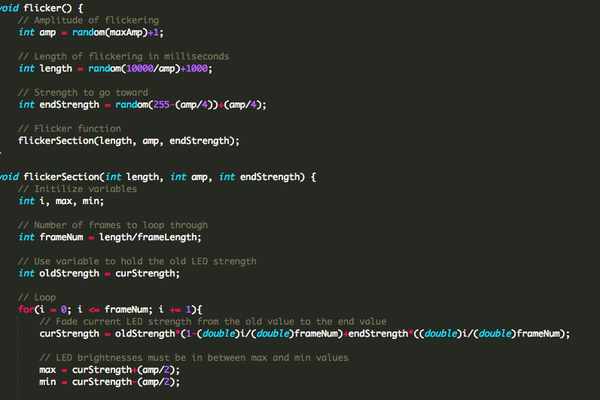
The last step is to let the average brightness change throughout each section. To do this we will need to start by storing the current brightness with a variable. We should also create a variable to decide what the final brightness should be. When we enter our for loop we will want to make the brightness fade slowly, so we can write some code that will match the ratio of future/current brightnesses to the ratio frames/length. Pseudocode:
loop (forever) {
	set LED range
	store current brightness
	set future brightness
	loop (section length) number of times {
		fade brightness
		flicker LEDs with range and brightness as parameters
		wait (frame length)
	}
}
Now that our code is done, let’s display our work!
Source: Realistic LED Candle