In this project, I’ll show you how to make your own 8×16 RGB LED Matrix using Arduino Uno/ Nano. An LED Matrix can show scrolling messages, display animations, music spectrum analyzer … With integrating NodeMCU, it can be used as small screen to show weather information from internet or any process values when it connect to Ethernet PLC system.
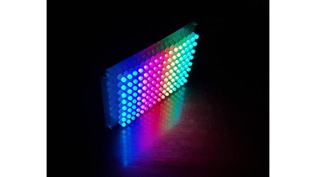
So, let’s watch my videos below and follow my instructables to start with building your own RGB LED Matrix.
- Auto-rotate scrolling message test (update on November 6th, 2018): Using MPU-6050 with Kalman filter to calculate the angle when we rotate Led Matrix.
- Animation Test
VU meter test: It shows music
volume unit by using fix FFT transformation. Led Matrix will be connected to music player by audio jack 3.5mm.
Smart Display Test: Connecting to PLC system
Smart Display Test: Showing weather information from Internet
Step 1: PARTS LIST & TOOL
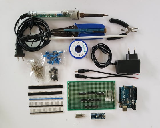
Electronic components & tools can be purchased from ebay as links below:
1. Electronic components:
- 1 x Arduino Uno/Nano
- 1 x NodeMCU
- 128 x Common Anode RGB LEDs
- 16 x A1013 Power NPN Transistors
- 2 x 74HC138 De-multiplexer
- 3 x 74HC595 Shift Register
- 3 x 0.1uF Electrolytic Capacitor
- 24 x 100Ω Resistor
- 16 x 560Ω Resistor
- 1 x Single-Side Copper Prototype PCB 9×15
- 1 x Double-Side Copper Prototype PCB 9×15
- 5 x 40Pin 2.54mm/19mm Long single row Headers
- 5 x Male & Female 40pin 2.54mm Header
- 1 x Power Supply Adapter 5V/2A
- 1 x DC Power Jack supply socket
- 1 meter x Rainbow Color Flat Ribbon Cable
2. Tools
- Wire Cable Striper
- Small Wire Cable Cutter
- 5mm ABS Styrene Plastic Rectangular Tube Or ABS Round Plastic Pipe
- 9V Battery & battery jack for LED testing
- Screwdriver
Source: D.I.Y SMART RGB MATRIX 8×16