I am new to Arduino and wanted a project which would teach me different things.
This got me involved with sound and the use of a LCD.
This project is based on the Instructable posted by bertus52x11 which you can find here http://www.instructables.com/id/After-Dinner-Reaction-Time-Tester/ .
While I did start with the bertus52x11 project I did make the following major mods :
1. I use 3 LEDS which change light pattern and the user needs to react to the correct pattern.
2. The original tested the time it took to release the button while I test the time it takes to hit the button.
3. I test 3 different times and record the accumulated time plus any miss hits or no hits at all.
As with the original project, this would be fun to use before and after a dinner party. It should confirm that too much of a good thing will slow your reflexes. I am anxious to do some testing. 🙂
Unfortunately I did not take pictures through out the build but I will try to explain and show what I did as best I can.
How it works:
1.Turn on with the ON/OFF switch
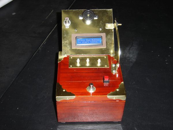
2. The first message will prompt you to press the red button to begin the testing
3. Then a screen will randomly tell you too look for 1 light on, 2 lights or 3 lights
4. The program will begin to randomly display 1, 2, or 3 lights with random noise for distraction purposes
5. As soon as you see the target light pattern, hit the reaction button.
6. After 3 times, a summary screen will appear
The program keeps track of what the target light pattern is and only when it displays the correct pattern does it start the timer. It also will only wait a short time. If you fail to see the correct pattern, it records it as a miss . Or if you hit the button too late or with a wrong pattern, it will record a miss. I arbitrarily add 2 seconds to the total for a miss.
Step 1: Video of the timer in action
The following 2 videos show how to use it and what happens when you push the button correctly or in correctly.
These Videos are available on the linked site.
Step 2: Stuff to get
Basically this is what is needed and an estimate of what it costs.
1. Arduino – I used a Uno but I am pretty sure others would work just fine – about 45.00 ( i think)
2. A box – I had this one already
3. a LCD – I got from Adafruit – a standard 16×2 – 12.00
4. 3 LEDs – I already had – can get from many places eg Radio Shack – couple of dollars
5. a buzzer – I already had – also Radio Shack – couple of dollars
6. wire and misc screws – I had
7. The brass items I got at Home Depot – the corner edges, the hinge and a piece of brass stock from which to cut various pieces.- maybe 15.00
Step 3: Putting it together
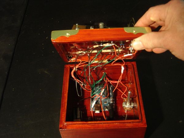
Since the Instructable by bertus52x11 was so easy to follow, I skipped the breadboarding step and went straight to installing everything in the box.
1. I put the brass corners on
2 I installed the hinge
3. I cut 2 pieces of brass from the bigger piece . One is used to hold the LEDs and the other for the buzzer and LCD.
4. I mounted the Arduino
5. attached the buzzer to the brass plate
6. attached the on/off button, the red start button and the reaction button
7. attached the plate with the 3 LEDs to the box
8 The 10k Pot is glued to the inside of the box
I find I can make a reasonable standoff for the Arduino by cutting a small piece from a length of tubing
All of these steps will depend on the box used and the placement of the switches.
Step 4: Connections to the Arduino
LEDS
– the 3 LEDS are connected to pins 6,7 and 8 with a 220 ohm resistor.
Buzzer
– one side connected pin 13 and the other to ground
ON/Off switch
– It is connected to the red wire coming from the positive side of the 9 volt battery which is in the box
Red Start Button
– This is a momentary switch which is connected to pin9
– the following link is good reference as to how to connect correctly(which I did not do at first)
http://www.arduino.cc/en/Tutorial/Button
The React Button
– Another Momentary switch connected to pin 10
2. A box
3. a LCD
4. 3 LEDs
For more detail: Reaction Timer using an Arduino