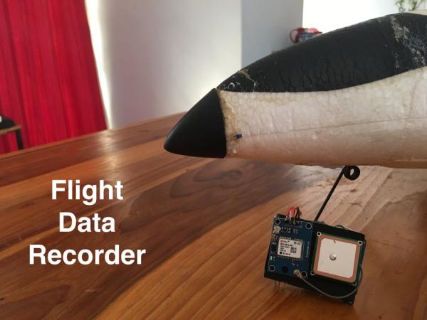
In this instructable I am going to be building a arduino based fight data recorder for RC vehicles, specifically RC aeroplanes. I am going to be using a UBlox Neo 6m GPS module connected to an arduino pro mini and a SD card shield to record the data. This project is going to record the Latitude, Longitude, Speed, Altitude and Battery voltage among other things. This data is going to be enriched for better viewing experience using Google Earth Pro.
Step 1: Tools and Parts
Parts:
- Ublox NEO 6m GPS module: ebay/amazon
- Micro SD card module: ebay/amazon
- Micro SD card(high speed or capacity not necessary): amazon
- Arduino pro mini: ebay/amazon
- FTDI programmer and corresponding cable : ebay/amazon
- Perfboard: ebay/amazon
- Hookup wire: ebay/amazon
- Header pins: ebay/amazon
- Rectifier diode: ebay/amazon
- 2x 1K ohm resistor: ebay/amazon
- 1500 micron cardboard
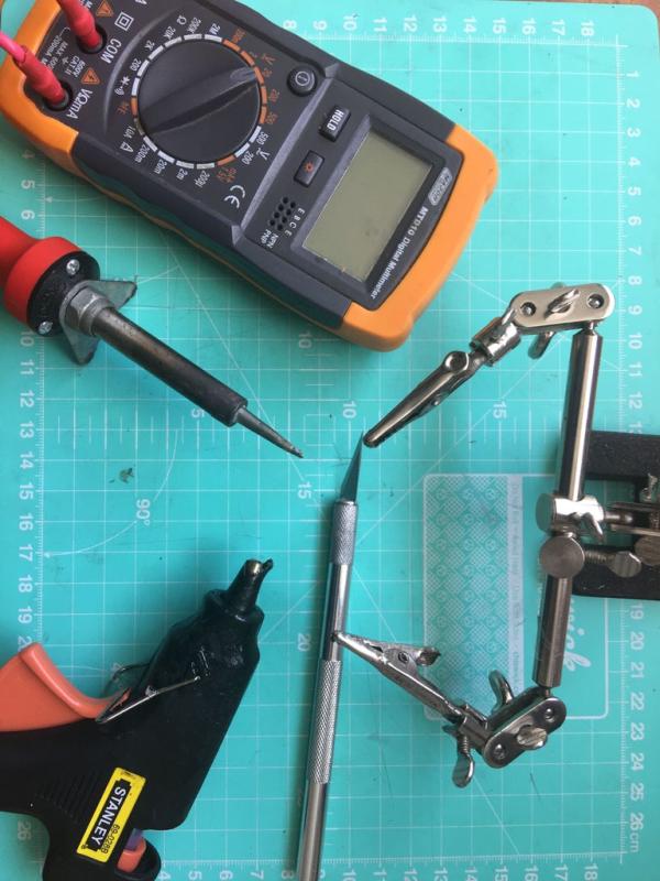
Tools:
- Soldering Iron and solder
- Hot glue gun
- Laptop or computer
- Multimeter(not strictly necessary but incredibly helpful)
- Helping hands(again not necessary but helpful)
- Craft knife
Optional:
- Items used for prototyping not necessary but very helpful
- Breadboard
- Arduino Uno
- Jumper Wires
Step 2: Theory and Schematic
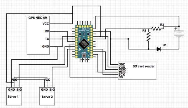
The brain of the device is the Arduino pro mini, it is powered from the RC vehicles(in my case an aeroplane) Li-Po battery balance port. I have this set up for a 2s battery but this can easily be changed to accommodate for other battery sizes.
This is piece is not complete I will update this instructable when the control surface reading is complete
- Servo1 will be my aeroplanes elevon motor while servo 2 will be my flight controller servo output.
The GPS module is receiving data from the GPS satellites in the form of NMEA strings. These string contain location information but aslo the exact time, speed, heading, altitude and lots of other useful data. Once a string has been received the information that is useful to this project is extracted using the TinyGPS code library.
This data along with battery voltage and elevon position is going to be written to the SD card at a rate of 1Hz. This data is written in CSV(comma-separated value) format and will be interpreted using google maps to plot a flight path.
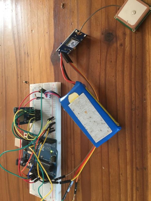
Step 3: Prototyping
NOTE: The GPS module connections are not shown above. GPS is wired as follows:
GND to Arduino ground
VCC to Arduino 5V
RX to Arduino digital pin 3
TX to Arduino digital pin 2
To test that all of the components are functioning correctly it is best to start by laying everything out on a breadboard as you don’t want to find out only after everything is put together that you have a defective part. The additional code library that will needed is the TinyGPS library the link can be found below.
The voltage tester code below just tests the voltage measuring circuit. The adjustment value needs to be changed to make the arduino read the correct voltage.
The Files code is used to test the SD card module and micro SD card to make sure both are reading and writing correctly.
The gpsTest code is used is used to make sure that the gps is receiving correct data and is configured correctly. This code will output your latitude, longitude and other live data.
If all of these parts are working together correctly then you can move on to the next step.
Step 4: Soldering and Wiring
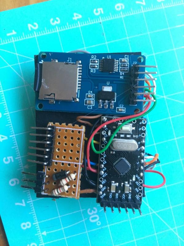
Before doing any of the soldering or wiring lay out all of your components on a piece of cardboard and cut it to the outside dimensions of the components. This is going to be your mounting plate for all your pieces.
Make the circuit board by cutting the perfboard to the smallest size feasible as weight and size are priorities. Solder the header pins in place along the edge of the cut perfboard, this is where the battery balance port and in future the control surface servo and flight controller will connect. Solder the 2 1k Ohm resistors and the rectifier diode in place according to the circuit diagram.
Solder the micro SD card module to the arduino’s pins according to the circuit diagram make the connections using the AWG 24 wire.
Make the connections between the perfboard and the arduino again according to the circuit diagram and using more of the same type of wire.
NOTE: The GPS is a electrostatic sensitive device be careful while soldering and never have any current running through any of the wires while making connections
Solder the GPS modules pins to the corresponding pins on the arduino using lengths of about 3-4cm(1-1.5in) of wire this give the GPS module enough slack to fold over to the other side of the backing card.
Check and double check the continuity for all the connections to make sure that everything is wired correctly.
Using hot glue mount the SD card module, The Arduino Pro Mini and you custom perfboard on one side of the cardboard and the GPS module and antenna on the other.
Once you have all the piece correctly wired and mounted to the cardboard its time to move on to the code.
Step 5: The Code
This is the code that runs on the final device. While this code is running the LED on GPS module will begin to flash as soon as the gps has a fix with more than 3 satellites. The LED on the arduino board will blink once as soon a the arduino starts up to show that the CSV file has been successfully created and then it will blink in time with the GPS LED when it is write to the micro SD card successfully. If the LED remains of the micro SD card cant be initialised and there is most likely a problem with your wiring or micro SD card.
This code will create a new CSV file every time the program is run they will be labeled “flightxx” where xx is a number between 00 and 99 that increases every time the program is run.
To get the current time field in the spreadsheet to be correct you need to convert the UTC(Coordinated Universal Time) to the correct time zone for you. For me the value is UTC +2.0 as that is the time zone I am located in but this can be changed in the code by altering the “timezone” float.
Step 6: Testing, Testing, Testing
By now you should have a working system, it’s time to test it, make sure that everything is functioning as expected.
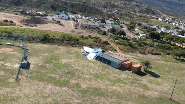
Once everything is working and you are getting an output on the spreadsheet that seems correct its time to make any fine adjustments. For example I originally had the device mounted to the bottom of my aeroplane with cable ties but after some investigation I figured out that that was reduce the amount of GPS satellites that could see at any one time by about 40%.
Test your system make sure everything works and refine it where necessary.
Step 7: Enriching Your Data
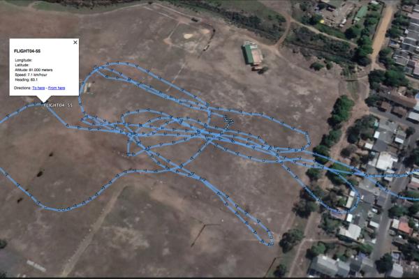
Now that you have a reliable system it is time to figure out how to display that data in a more readable fashion. The spreadsheet is fine if you want the exact speed at any one time or if you want to check exactly how you vehicle was behaving when you performed a certain action but what if you want to plot an entire flight on a map or see each data point in a more readable fashion this is where data enrichment is helpful
To view our data in a more readable manner we are going to be using google earth pro, you can click here to go and download it.
Now you have to convert the CSV file into a GPX file that can be read more easily by google earth using GPS visualizer. Select output GPX, upload your CSV file and download the converted file. Then open the GPX file in google earth and it should automatically import and plot all of the data into a nice flight path. This also contains additional information like the heading at any point in time.
NOTE: I have removed the lat, long data from the photos as I do not want to disclose my exact location.
Step 8: Conclusion and Posible Improvements
So over all I am very happy with how this project turned out. I enjoy having data from all my flights. however there are a few thing I want to work on.
Most obviously i want to be able to read the exact position of the control surfaces. I have most of the hardware in place for this but i need to enable the use of it in the code. There are still some technical challenges to overcome.
I would also like to add a barometer for more accurate altitude data, as currently the gps altitude data doesn’t seem much more than an educated guess.
I think that adding a three axis accelerometer would be cool so that I could see exactly how much g-force the plane is enduring at any time.
Maybe create an enclosure of some sort. Currently with the exposed components and wiring its not very elegant or robust.
Please let me know if you come up with any improvements or modifications to the design I would love to see them.
Source: RC Flight Data Recorder/Black Box