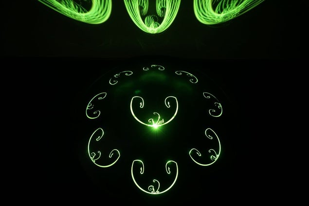
This project is a small, battery-powered LED ring that fits perfectly inside of your Rav Vast drum. It uses color-changing RGB LEDs and a microphone that allows you to change the color or pattern with changes in volume.
You don’t need any special skills for the construction (though you may pick some up along the way)
Step 1: Tools and Materials
Ingredients:
- Arduino Gemma v2
- 16 LED NeoPixel Ring
- 3.7v 500mAh li-poly battery
- Li-poly battery charger
- Microphone amplifier (optional if you don’t care about being sound-reactive)
Total cost: $40.75 + tax + shipping (as of this writing)
Tools:
- Soldering Iron and solder
- Wire strippers
- #22 gauge solid core wire
- Computer capable of running the Arduino IDE
- Breadboard, alligator clips, and jumper cables (optional. Used for testing)
- Reusable adhesive (I used Blu Tack)
Step 2: Set Up the Arduino IDE

For this project you will need to program the Gemma microcontroller. We are going to do that with the Arduino IDE, so go ahead and download it here: https://www.arduino.cc/en/main/software
Once it has been downloaded, we’re going to need to add support for the Gemma board. Adafruit has an excellent guide for this here: https://learn.adafruit.com/add-boards-arduino-v164/setup
Lastly, you will need to install the Adafruit_NeoPixel library. The guide for that is here: https://learn.adafruit.com/adafruit-neopixel-uberguide/arduino-library-installation
If you are on Windows, you may also need to install the drivers for the programmers: https://learn.adafruit.com/usbtinyisp/drivers
Step 3: Test the LED Ring
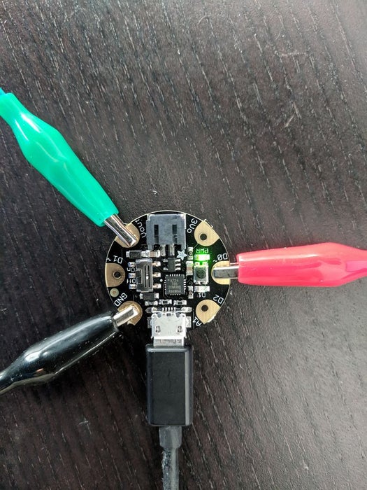
Plug the Gemma into your computer with a micro USB cable.
Attach alligator clips to the Gemma and the Neopixel ring. We want the following connections:
- [Gemma] Vout -> [ring] POWER 5V DC
- [Gemma] GND -> [ring] SIGNAL GROUND
- [Gemma] D0 -> [ring] DATA INPUT
Now we need to program your Gemma. Open the Arduino IDE. First we need to configure the Arduino IDE to use the correct settings.
- Go to the menu “Tools -> Board” and make sure that “Adafruit Gemma” is selected.
- Go to the menu “Tools -> Programmer” and make sure that “USBtinyISP” is selected.
Now download this file and open it in the Arduino IDE (or copy/paste it into your sketch): https://raw.githubusercontent.com/stevearc/ravlight/master/ravlight.ino
There is a button on the Gemma next to the power light. When you press it, it enters “programming mode” and the orange light will begin to flash. To upload your code, press the button and while the orange light is flashing, go to “Sketch -> Upload” (Ctrl+U) in the Arduino IDE.
After you upload your code, the LED ring should light up and the colors should circle around! If they do not, check the connections with the alligator clips. Sometimes they can be finicky.
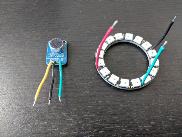
Step 4: Solder Wires to the LED Ring
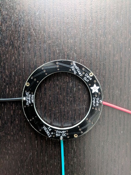
Now that you have confirmed that the LED ring works, solder wires to the ring in place of the alligator clips. Make sure you have more wire than you think you need, so you can trim it down to size later.
If you have never soldered before, try watching some instructional videos first. This was my first time soldering as well, and YouTube proved to be a great resource.
Step 5: Solder Wires to the Microphone
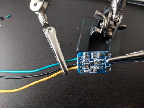
Now we’re going to need to wire up the microphone. I found that the alligator clips were too large to get a good connection, so I skipped straight to the soldering. Again, make sure you leave a little extra length on the wires so you can trim them to size later.
Step 6: Test the Whole Circuit
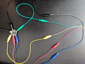
Attach two more alligator clips to the Gemma: one on the A1 (analog input) pad, and one on the 3V (3 volt output) pad.
Attach all alligator clips to jumper cables, and plug those jumper cables into a breadboard. Now plug your LED ring and microphone into the breadboard. If you want to learn more about how the breadboard works, I recommend skimming https://www.instructables.com/id/Breadboards-for-…
The only concepts you need to know for this are:
- The two columns of holes on either side of the breadboard are connected vertically
- The rows of holes towards the center of the breadboard are connected horizontally
You want these connections:
- [Gemma] Vout -> [ring] POWER 5V DC
- [Gemma] GND -> [ring] SIGNAL GROUND
- [Gemma] D0 -> [ring] DATA INPUT
- [Gemma] 3Vo -> [mic] VCC
- [Gemma] GND -> [mic] GND
- [Gemma] A1 -> [mic] OUT
The wiring shown is quite messy, but we’re just using this to test the circuit.
After everything is wired together, try changing the mode in the code:
#define MODE 3
Reprogram the Gemma (by pressing the button on the board and Ctrl+U in the Arduino IDE). You should now see the lights react to sound!
Step 7: Prepare to Solder the Board
Trim the wires of the LED ring and microphone down. Position the Gemma in the center of the ring and bend the wires into the proper place. Remember that you want:
- [Gemma] Vout -> [ring] POWER 5V DC
- [Gemma] GND -> [ring] SIGNAL GROUND
- [Gemma] D0 -> [ring] DATA INPUT
Once the wires are the appropriate length and positioned correctly, proceed to the next step.
Step 8: Solder the Ring to the Board
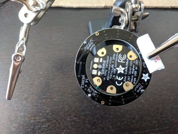
For this step we only want to solder the D0 and Vout pads. Remember that the ring and the microphone share the GND pad, so we will have to wait until the microphone is in-place to solder it. By soldering the other two first, it helps to hold the ring in position for when you attach the microphone.
Step 9: Solder the Microphone to the Board
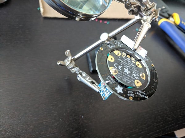
Put the microphone in place on top of the board and solder all of the connections. Remember that we want to connect:
- [Gemma] 3Vo -> [mic] VCC
- [Gemma] GND -> [mic] GND
- [Gemma] A1 -> [mic] OUT
You can tell that even though I am garbage at soldering, it’s easy to end up with something functional. The Gemma is very forgiving.
Source: Rav Vast LED Drum Light