Summary of Project Suite Bros: Voice Activated LED Friendship Photoset (Arduino, Bluetooth, Crafts)
This project builds a voice-activated friendship photoset called Project Suite Bros: a framed display with LEDs behind photos that are controlled via an Android speech-recognition app and an HC-05 Bluetooth-connected Arduino. Voice commands sent as *command# strings trigger Arduino code to turn individual LEDs, groups, or a party animation on and off. The guide covers materials, photo/LED mounting, Bluetooth wiring (use 3.3 V for HC-05), LED pin assignments (pins 2–13), and the Arduino sketch adapted from ASCAS.
Parts used in the Project Suite Bros:
- HC-05 Serial Bluetooth Module
- Assorted LEDs (approximately 12)
- Jumper Cables
- Arduino UNO
- Power Supply for Arduino (wall plug)
- USB cable for Arduino
- Drip Mat (plastic cover for decoration)
- Construction Paper
- Plastic Microwave Tray (used as photoset frame)
- Baby pack lunchboxes (LED containers)
- Solderless Breadboard (for testing)
- Soldering Tool Kit
- Basic Power Drill
(and partner-in-crime, Abbie). Now, I’m off to the next stage of my life, so I decided to build this friendship photoset for Kevin and Briton to remember our golden era. We called ourselves: “The Suite Bros”.
This project is actually an extension of the “Voice Activated Arduino (Bluetooth + Android) by ASCAS. I highly advise you guys to read his project first! ASCAS really simplified the fundamentals of the project down super well.
It’s been a little more than a year since the last time (and the first time) I took Electronics at Pomona College and learned to use the Arduino. I thought ASCAS’s project was fun and easy-to-learn. He has great project. Check him out when you can!
HOW PROJECT SUITE BROS WORKS
It’s a DIY photoset that has LEDs inserted in the frame and in the back of photos that are activated by your voice commands via an Android’s speech recognition app. The app is called “Android Meets Robots: Voice” by SimpleLabsIN. This app converts your voice commands to data strings and sends them to your Arduino via Bluetooth. You can build the photoset in any way you want. I just want to show you how I built mine in this Instructable.
 Step 1: Materials and Equipment
MATERIALS
- HC-05 Serial Bluetooth Module
- Assorted LEDs – I used about 12 LEDs
- Jumper Cables
- Arduino UNO
- Power Supply for Arduino Electronics Wall Plug
- USB for Arduino
- Drip Mat – Just a plastic cover I used to write “Always a party when we’re together”. For crafts purposes.
- Construction Paper – Not much needed
- Plastic Microwave Tray – Used this as the photoset frame. It was $1.50 at the DAISO store
- Baby pack lunchboxes – Used to place underneath photos and to contain LEDs. $1.50 at DAISO
EQUIPMENT
- Solderless Breadboard (for testing)
- Soldering Tool Kit – Buy a decent one for yourself!
- Basic Power Drill – Only need it to drill a hole through the photoset frame
Step 2: Understand the Basics
Read through this Instructable to make sure you understand the basics of this project:
Step 3: Prepare your photos and LED containers
- Print out your photos and make sure they fit the LED containers (aka. baby pack lunchboxes).
- Use the LED containers to draw a circle on your photos.
- Cut construction paper (pick any color you like) so that it wraps around the LED containers on the sides. Then, attach your photo on the bottom of the LED container with tape or glue.
- Find out where you want to place your photos + LED container units on your frame board.
- (Optional) I laminated the photos, so they’d look more cool.
- Drill holes where you wish for your LEDs to show up.
- I drilled about 12 holes – two for each photo, two in the center, one on each side, and two on the bottom.
- Add any creative text or decorations on the photos.
- I cut out the words “THE SUITE BROS” and placed each word on each photo. Then, I taped on yellow dividers.
Step 4: Assemble the Bluetooth
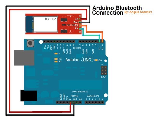
This step is referenced directly from ASCAS’s instructions. I believe he made very clear instructions and a great diagram. I put this here for your convenience. Remember to connect to 3.3 V and not 5 V (like the diagram).
“Grab some jumper cables and power the Bluetooth module with 3.3 volts. Remember, the bare HC-05 run on 3.3v and not on 5v. Now connect the RX (pin #0) of the Arduino to the TX pin of the Bluetooth module and the TX (pin #1) of the Arduino to the RX pin of the Bluetooth module. (refer to the image above)
Step 5: Assemble the LEDs
The schematic seems quite complicated, but it’s not that bad. In my diagram, I connected LEDs to basically all the pins left.
- Connect LED 1 To Pin #2
- Connect LED 2 To Pin #3
- Connect LED 3 To Pin #4
- Connect LED 4 To Pin #5
- Connect LED 5 To Pin #6
- Connect LED 6 To Pin #7
- Connect LED 7 To Pin #8
- Connect LED 8 To Pin #9
- Connect LED 9 To Pin #10
- Connect LED 10 To Pin #11
- Connect LED 11 To Pin #12
- Connect LED 12 To Pin #13
I forgot to purchase blank circuit boards, so my actual setup looks like a complete mess. I basically soldered the ends of jumper cables to ends of LEDs. Lesson learned. But hey, it works!
So yes, I suggest you to use blank circuit boards to connect all of the GND components of the LEDs
Step 6: Programming your Arduino
This next part is also very important. Once again, ASCAS has given an outstanding explanation. I’ve pasted it here below (but please check his page):
Understanding The App
Before you program the arduino, you must first learn how the app works. The app work by recognizing your voice command, it will then display the words that you’ve spoken then sending data/ strings to the arduino via bluetooth. What’s a string? A string is like a word, you can make conditional statements out of it [ex: if (voice == “*computer on”) {// turn Pin #2 on} ]. The “voice” is your string, “==” is your condition (means equal to), “*computer on” is your command and the code inside the curly-braces “{ }” are the codes to be executed once your string matches the command condition.
What’s the format of the string? How does it know when the next command kicks in? How does it differentiate a set of words from a new command? The app sends strings in this format *command#, the asterisk (*) indicates the start of a new command and the hash-tag (#) indicates the end of a command. I was able to remove the hash-tag (#) after each word in the conditional statement was not able to remove the asterisk (*). You’ll need to start your command condition with an asterisk otherwise the sketch will not work.
How Can I Change The Commands?
You can see that the “*TV on” is highlighted from the image above. If you want to change the command to ,humm let’s say “open garage door”, you can replace the “*TV on” with “*open garage door”. Always remember to start the command with an asterisk.
THE CODE
//Voice Activated Arduino (Bluetooth + Android) Coded By:
Angelo Casimiro (4/27/14)
//Adapted By: Chloe Shih (8/25/14)
//PROJECT SUITE BROS
//Feel free to modify it but remember to give credit
String voice;
String voice2;
int
led1 = 2, //Connect LED 1 To Pin #2
led2 = 3, //Connect LED 2 To Pin #3
led3 = 4, //Connect LED 3 To Pin #4
led4 = 5, //Connect LED 4 To Pin #5
led5 = 6, //Connect LED 5 To Pin #6
led6 = 7, //Connect LED 6 To Pin #7
led7 = 8, //Connect LED 7 To Pin #8 (bottom pins begin here)
led8 = 9, //Connect LED 8 To Pin #9
led9 = 10, //Connect LED 9 To Pin #10
led10 = 11, //Connect LED 10 To Pin #11
led11 = 12, //Connect LED 11 To Pin #12
led12 = 13; //Connect LED 12 To Pin #13
//————————–Call A Function——————————-//
void allon(){
digitalWrite(led1, HIGH); // kevin
digitalWrite(led2, HIGH); // briton
digitalWrite(led3, HIGH); // chloe
digitalWrite(led4, HIGH); // kevin’s color
digitalWrite(led5, HIGH); // briton’s color
digitalWrite(led6, HIGH); // chloe’s color
digitalWrite(led7, HIGH); // yellow middle
digitalWrite(led8, HIGH); // green middle
digitalWrite(led9, HIGH); // blue side
digitalWrite(led10, HIGH); // red side
digitalWrite(led11, HIGH); // white bottom
digitalWrite(led12, HIGH); // yellow bottom
}
void alloff(){
digitalWrite(led1, LOW); // kevin
digitalWrite(led2, LOW); // briton
digitalWrite(led3, LOW); // chloe
digitalWrite(led4, LOW); // kevin’s color
digitalWrite(led5, LOW); // briton’s color
digitalWrite(led6, LOW); // chloe’s color
digitalWrite(led7, LOW); // yellow middle
digitalWrite(led8, LOW); // green middle
digitalWrite(led9, LOW); // blue side
digitalWrite(led10, LOW); // red side
digitalWrite(led11, LOW); // white bottom
digitalWrite(led12, LOW); // yellow bottom
}
void partyloop(){
while (voice == “*party on”) {
digitalWrite(led4, HIGH); // turn the LED on (HIGH is the voltage level)
digitalWrite(led5, HIGH);
digitalWrite(led12, HIGH); // bottom yellow
digitalWrite(led6, HIGH);
digitalWrite(led7, HIGH);
digitalWrite(led8, HIGH);
digitalWrite(led9, HIGH);
digitalWrite(led10, HIGH);
delay(300); // wait for half a second
digitalWrite(led1, HIGH);
digitalWrite(led3, HIGH);
digitalWrite(led4, LOW); // turn the LED off by making the voltage LOW
digitalWrite(led6, LOW);
digitalWrite(led7, LOW);
digitalWrite(led10, LOW);
delay(100);
digitalWrite(led3, LOW);
digitalWrite(led1, LOW);
digitalWrite(led5, LOW);
digitalWrite(led12, LOW); // bottom yellow
digitalWrite(led2, HIGH);
digitalWrite(led11, HIGH); // bottom white
digitalWrite(led4, HIGH);
digitalWrite(led6, HIGH);
digitalWrite(led8, LOW);
digitalWrite(led7, HIGH);
digitalWrite(led9, LOW);
digitalWrite(led10, HIGH);
delay(500);
digitalWrite(led6, LOW);
digitalWrite(led1, HIGH);
digitalWrite(led3, HIGH);
digitalWrite(led4, LOW);
digitalWrite(led5, HIGH);
digitalWrite(led12, HIGH);
digitalWrite(led8, HIGH);
digitalWrite(led7, LOW);
digitalWrite(led9, LOW);
digitalWrite(led10, HIGH);
delay(600);
digitalWrite(led1, LOW);
digitalWrite(led2, LOW);
digitalWrite(led11, LOW); // bottom white
digitalWrite(led5, LOW);
digitalWrite(led12, LOW); // bottom yellow
digitalWrite(led3, LOW); // voice: “*party on” at this point
digitalWrite(led7, HIGH);
digitalWrite(led8, LOW);
digitalWrite(led9, HIGH);
digitalWrite(led10, LOW);
Serial.println(“in loop”);
newVoice(); // receives new voice.
if (!(voice2.equals(voice)) && voice2 != “”) {
voice = voice2;}}
if (voice != “*party over” && voice != “*party off” && voice != “*party poop” && voice != “*party pooper” && voice != “*lights off” && voice != “*party of”) {
voice = “*party on”;
voice2 = “”;
partyloop();}
alloff(); // turn all lights off}
//———————————————————————–//
void newVoice() {voice2 == “”; // clear voice
while (Serial.available()){ //Check if there is an available byte to read
delay(10); //Delay added to make thing stable
char c = Serial.read(); //Conduct a serial read
if (c == ‘#’) {break;} //Exit the loop when the # is detected after the word
voice2 += c; //Shorthand for voice = voice + c}
if (voice2.length() > 0) {
Serial.println(voice2);}}
//———————————————————————–//
void setup() {
Serial.begin(9600);
pinMode(led1, OUTPUT);
pinMode(led2, OUTPUT);
pinMode(led3, OUTPUT);
pinMode(led4, OUTPUT);
pinMode(led5, OUTPUT);
pinMode(led6, OUTPUT);
pinMode(led7, OUTPUT);
pinMode(led8, OUTPUT);
pinMode(led9, OUTPUT);
pinMode(led10, OUTPUT);
pinMode(led11, OUTPUT);
pinMode(led12, OUTPUT);}
//———————————————————————–//
void loop() {
while (Serial.available()){ //Check if there is an available byte to read
delay(10); //Delay added to make thing stable
char c = Serial.read(); //Conduct a serial read
if (c == ‘#’) {break;
} //Exit the loop when the # is detected after the word
voice += c; //Shorthand for voice = voice + c}
if (voice.length() > 0) {
Serial.println(voice);
//———————————————————————–//
//———-Control Multiple Pins/ LEDs———-//
if(voice == “*turn all on”) {allon();} //Turn Off All Pins (Call Function)
else if(voice == “*turn all off” || voice == “*turn off” || voice == “*party over” || voice == “*party off” || voice == “*party of” || voice == “*party poop” || voice == “*lights off” || voice == “*lights of”){alloff();} //Turn On All Pins (Call Function)
else if(voice == “*party on”){partyloop();}
else if(voice == “*friends on” || voice == “*the suite bros on” || voice == “*the sweet Bros” || voice == “*suite bros on” || voice == “*sweet Bros on”) {
digitalWrite(led1, HIGH); // kevin
digitalWrite(led2, HIGH); // briton
digitalWrite(led3, HIGH); // chloe}
 else if(voice == “*side lights on”) {digitalWrite(led9, HIGH); digitalWrite(led10, HIGH);}
//———-Turn On One-By-One———-//
else if(voice == “*Kevin on” || voice == “*kevin on”) {digitalWrite(led1, HIGH);}
else if(voice == “*Briton on” || voice == “*Brighton on” || voice == “*Abbie on” || voice == “*abbie on”) {digitalWrite(led2, HIGH);}
else if(voice == “*Chloe on”) {digitalWrite(led3, HIGH);}
else if(voice == “*smile on”) {digitalWrite(led11, HIGH);}
else if(voice == “*message on”) {digitalWrite(led8, HIGH); digitalWrite(led7, HIGH);}
else if(voice == “*red on”) {digitalWrite(led10, HIGH);}
else if(voice == “*blue on”) {digitalWrite(led9, HIGH);}
//———-Turn Off One-By-One———-//
else if(voice == “*Kevin off” || voice == “*kevin off”) {digitalWrite(led1, LOW); digitalWrite(led4, LOW);}
else if(voice == “*Briton off” || voice == “Brighton off” || voice == “*abbie off” || voice == “*Abbie of” || voice == “*abbie of” || voice == “*Abbie off”) {digitalWrite(led2, LOW);digitalWrite(led5, LOW);}
else if(voice == “*Chloe off”) {digitalWrite(led3, LOW);digitalWrite(led6, LOW);}
else if(voice == “*message off” || voice == “*message of”) {digitalWrite(led7, LOW); digitalWrite(led8, LOW);}
else if(voice == “*red off” || voice == “*red of”) {digitalWrite(led10, LOW);}
else if(voice == “*blue off” || voice == “*blue of”) {digitalWrite(led9, LOW);}
else if(voice == “*smile of” || voice == “*smile off”) {digitalWrite(led11, LOW); digitalWrite(led12, LOW);}
//———-Turn Off in Group———-//
else if(voice == “*friends off” || voice == “*friends of” || voice == “suite bros off” || voice == “*sweet Bros of” || voice == “*sweet Bros off” || voice == “*sweet bros off” || voice == “*sweet bros of”) {
digitalWrite(led1, LOW); // kevin
digitalWrite(led2, LOW); // briton
digitalWrite(led3, LOW); // chloe}
//———————————————————————–//
voice=””;}} //Reset the variable after initiating
For more detail: Project Suite Bros: Voice Activated LED Friendship Photoset (Arduino, Bluetooth, Crafts)
- How does the photoset get voice commands?
The Android app Android Meets Robots: Voice converts speech to strings and sends them via Bluetooth to the Arduino. - Can I use any Bluetooth module voltage?
No, the HC-05 must be powered with 3.3 V not 5 V. - What format does the app send commands in?
The app sends strings in the format *command# where * marks the start and # marks the end of a command. - Which Arduino pins are used for LEDs?
The project connects LEDs to digital pins 2 through 13 on the Arduino UNO. - How are multiple LEDs turned on at once?
The sketch includes functions like allon() and alloff() and conditional checks for voice strings to control multiple pins. - What should I use to mount LEDs behind photos?
The author used baby pack lunchboxes as LED containers taped to photos and placed them on a plastic tray frame. - How is the Bluetooth module wired to the Arduino?
Connect HC-05 TX to Arduino RX (pin 0) and HC-05 RX to Arduino TX (pin 1), and power HC-05 with 3.3 V. - How does the party animation stop?
The partyloop function checks for new voice input and exits when voice changes to commands like *party over or *party off, then calls alloff(). - Do I need a circuit board for GND connections?
The author recommends using blank circuit boards to connect all LED grounds, because soldered jumper cables were messy.