Summary of Programming a ATtiny2313 with Aceduino
The article explains how to program an ATtiny2313 chip using an ACEDUINO, a Philippine Arduino clone. The author details troubleshooting steps after failing with common methods and successfully implementing a solution involving specific board configurations in the IDE, including selecting 8MHz or 1MHz options. The guide covers circuit setup with resistors and capacitors, loading the ArduinoISP sketch onto an Arduino Duemilanove, and burning the blink sketch to the ATtiny2313.
Parts used in the ACEDUINO Project:
- ACEDUINO (Philippine Arduino clone)
- ATtiny2313 chip
- Arduino Duemilanove w/ ATmega328
- Fritzing software for board design
- 10K ohm pullup resistor
- 10uF electrolytic capacitor
- Status LED (not used in this project)
- Blink sketch
- ArduinoISP sketch
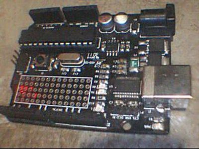
What is an ACEDUINO? It is the Philippine Arduino clone. See pic 2 and 3.
Quote from Fall Electronics:
If you have already tried you have found out you can’t use the ATTiny chips in Arduino. This is because it doesn’t have the cores for the chips. A core in this context is a bunch of code and text that tells Arduino which pins are which, how fast the clock can go, how to upload the program, which functions the chip knows… basically it’s an in-depth profile of the chip.
I have tried almost every way to program an ATtiny2313 with an Arduino that i could find. For what ever reason none of them ever worked. If you have had such a problem and want to remedy it or are just the curious type then read on.
Step 1: Not working
Coding isn’t old hat for me so all of these seamed rather complicated.
Here is some of the more common ones i had tried that i couldn’t get to work: Ladyada, ToasterBotics, Hilow. I imagine these are working for a lot of people but how, i dunno.
In the picture that shows my IDE you can see the list of boards i have to choose from. There is one choice for the ATtiny2313 with no clock options.
When ever i select this option and try to compile say the blink sketch, it will always through an error. Any sketch, any time, any where.
This was one the procedure that i used here. If you can get this to work you are a better man than I.
Step 2: Working
This procedure to me was clear and simple to install.
Now you can see the ATtiny2313 has 2 board choices . As well as many others, but we are only concerned with the ATtiny2313 at this point.
ATtiny2313 @ 8MHz
ATtiny2313 @ 1MHz
Now were getting somewhere.
HERE is the magic answer for me. Its in Spanish but it translates well. When i followed there procedure all the stars aligned and spit out a programmed chip. I was very elated as i have been working on this for some 9 mo or so. Off and on.
Step 3: Setup for Programming
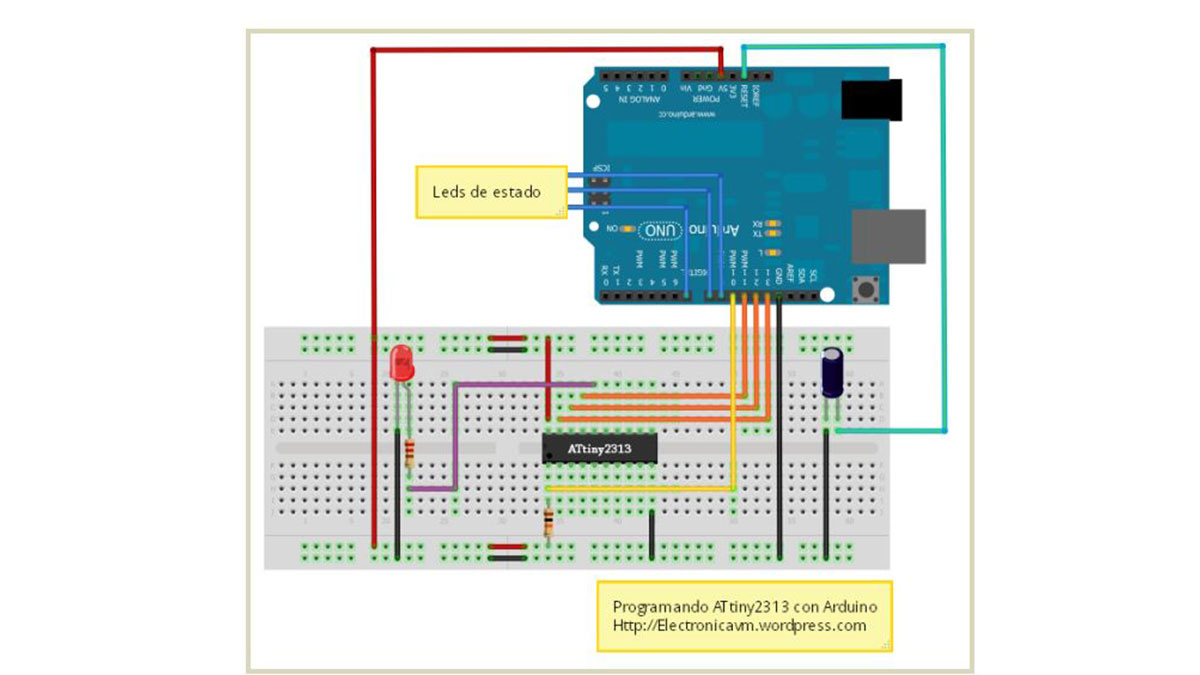
This board setup was made in Fritzing by Fall Electronics.
I did not use the ( Led de estado ). They are status LED’s for programming.
There is a 10K ohm pullup resistor on the reset of the chip. Pin 1 to VCC.
There is a 10uF electrolytic capacitor on the reset of the Arduino. From the reset to ground.
These are different resets and they are not connected together in the circuit.
After you are successful with setting up the circuit then the ATtiny2313 files and confirmed they are available in the IDE you will need to set up your Arduino for programming.
In my 3rd picture you can see i am loading the ArduinoISP sketch. This makes the Arduino able to program other chips. Also note at the bottom of the IDE i have the ATmega328 board chosen to load the ArduinoISP sketch into. The complete board name is blocked in the picture so here it is: Arduino Duemilanove w/ ATmega328. My port is on COM2.
Now that you have that completed you can continue to set up to program the ATtiny2313.
If you are using the 1MHz then your selection should look like pic #4.
Pic #5 shows the board that is selected at the bottom of the IDE.
From there you can load the blink sketch or what ever and burn it to the chip.
What pin is the LED connected on in the diagram?
Looks like pin 16 on the chip.
What number do we use in the IDE?
You can consult the chart and get the answer or if you prefer i will do it for you, it is 13.
Same as when you loaded the blink sketch so it doesn’t need to be changed.
Attiny2313
For more detail: Programming a ATtiny2313 with Aceduino
- Why could I not use ATTiny chips in my standard Arduino?
The standard Arduino lacks the necessary cores, which are code profiles defining pins, clock speeds, upload methods, and functions. - Which common programming methods failed for the author?
Ladyada, ToasterBotics, and Hilow procedures did not work for the author despite being functional for others. - What specific board choices appear for the ATtiny2313 in the working IDE setup?
The IDE shows two choices: ATtiny2313 @ 8MHz and ATtiny2313 @ 1MHz. - How is the reset pin connected on the ATtiny2313 circuit?
A 10K ohm pullup resistor connects pin 1 to VCC on the chip reset. - Where is the 10uF capacitor placed in the circuit?
The 10uF electrolytic capacitor connects from the reset pin to ground on the Arduino side. - Which sketch must be loaded into the Arduino to make it program other chips?
You need to load the ArduinoISP sketch into the Arduino Duemilanove w/ ATmega328. - On which pin is the LED connected in the diagram?
The LED is connected on pin 16 of the chip. - What number should be used for the LED in the IDE code?
You should use the number 13, which is the same as the standard blink sketch.