PLEASE CHECK THE NEW IMPROVED WEATHER STATION LINEAMETEOSTAZIONE v2.0!
LINK VERSION 2.0 LINEAMETEOSTAZIONE HERE
LineaMeteoStazione is a complete weather station which can be interfaced with professional sensors from Sensirion as well as some Davis Instrument component (Rain Gauge, Anemometer)
The project is aimed as DIY weather station but just requiring the assembly part, because the boards will already be given programmed by me as well as the complete PCB. The code will be shared Opensource for the people who wants to try to do it from the beginning or modify it!
YOU CAN FIND THE WEATHER STATION IN WeatherCloud, Wunderground and LineaMeteo (Italian Weather network!) (Anemometer is not Installed) and here also a Version in THINGSPEAK for the comparation between SHT3x and SHT1x. I’m using the SHT1x at the moment to monitor the temperature inside the weatherproof box, but you can use it also to monitor ground temperature and humidity or other purposes!
Please Note (The links above will go Offline because the weather station will be removed in February 2021 because I’m moving in an apartment)
YOU CAN FIND ALL THE INFO AND CODE UPDATE HERE IN GITHUB
Step 1: List of Components
It works with a combination of ESP8266 and ESP32 development boards and is composed mainly of 3 devices:
1. DEVICE 1: WEMOS D1 MINI PRO(New Version) + designed PCB (Need to be installed OUTSIDE) AND SOLAR PANEL This is the part which will be outside and it consist in one development board and the PCB. It is used to collect the weather data which will be sent to the Firebase of Google. The data is collected in real time from each sensor, but the upload time is selectable in the settings of the weather station which will be explained in the manual after. The maximum and minimum temperature will be collected in real time. Below the photo of the complete unit:
2. DEVICE 2: WEMOS D1 MINI PRO(Old Version) + BMP180 pressure
This is the part that handle all the network communications and it also collect the data from the Firebase of Google. The duties of the board consist in: Collecting the data Sharing some data to an IP Address in a format ready to be used to communicate with LineaMeteo weather network. Send Data to weathercloud Send Data to wunderground Send Data to Thingspeak
The case is 3D printed from https://www.thingiverse.com/thing:4081064
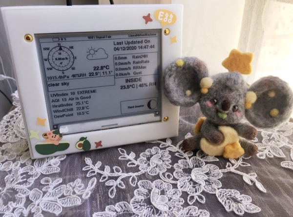
3. DEVICE 3: LOLIND32 ESP32 + PCB designed + INK Display + BME680
This is the part that just handle the visualization of the data on the display and it has also a sensor that collects data of air quality, pressure, temperature and humidity. The display used is a 4.2 Inch ink display, can be used a WaweShare or GoodDisplay brands.
The case is 3D printed from:
Box for ePaper + ESP32 Information Display by sidoh10 – Thingiverse
Step 2: DEVICE 2: Interface to Wi-Fi and Firebase Google
**SEE THE MANUAL OF THE WEATHER STATION IN THE LINK OF GITHUB ABOVE FOR MORE SPECIFIC DETAILS**
First of all we need to create a Firebase account. To do that you will need an account Google which you can create if you don’t already have one.
To setup the Firebase account you need to follow the following steps:
1. Go to FIREBASE and click on ‘Get Started’
Sign IN to your Google account
2. Click on ‘Add a project’ ‘Aggiungi progetto’
3. Give a name to your project! Click ‘Continue’ ‘Continua’. Follow the steps and Create the project. Use the default account for Firebase.
4. ‘Go on ‘project overview’ ‘Panoramica del progetto’ on top and select ‘project settings’ ‘Impostazioni progetto’
5. Click on ‘Service Account’ ‘Account di Servizio’ and ‘Create Service Account’ ‘Crea account di servizio’
6. Go back to ‘Project Overview’ and Create Realtime Database ‘Crea database’ and follow the steps and select the nearest location for the database.
7. ALL DONE! Now save your project link that you can find in the real time database and also the secret that you can find ‘Service Account’ ‘Account di servizio’ under ‘Database Secret’ ‘Segreti Database’
You will need just the one highlighted in the picture below and the database secret to program the weather station! To send you the board already programmed I will need those credentials and also for the you to program the board.
Step 3: SETUP WI-FI (SEE MANUAL ON GITHUB FOR IMAGES)
To setup the Wi-Fi connection follow the following steps:
· Plug the USB cable from DEVICE 2 into a USB port (you can use a normal charger for your phone or whatever USB port available, for example on your router(recommended option))
· Once DEVICE 2 is ON you will find it in the Wi-Fi connections available on your smartphone or computer with the name of LineaMeteoStazioneR.
· Try to connect and it will ask a password. PASSWORD: LaMeteo2005
· Click on configure Wi-Fi and select your Wi-Fi network and enter your password and click Save. Now the DEVICE 2 will try to connect and if fails you will be required to start again the procedures followed before.
· After the DEVICE 2 is connected, go back to your Realtime database and you will see that many information have appeared.
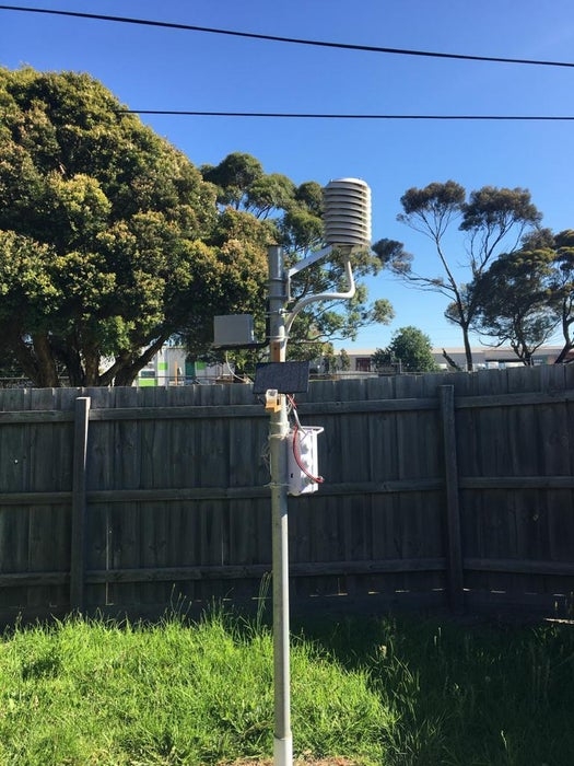
Step 4: Setup DEVICE 1(Outside)
This is the installation which requires to secure the weather station outside. A solar radiation shield Is required for the ambient temperature and humidity sensor. Is also required a weather proof box for the correct storage of the battery and PCB.
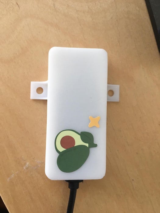
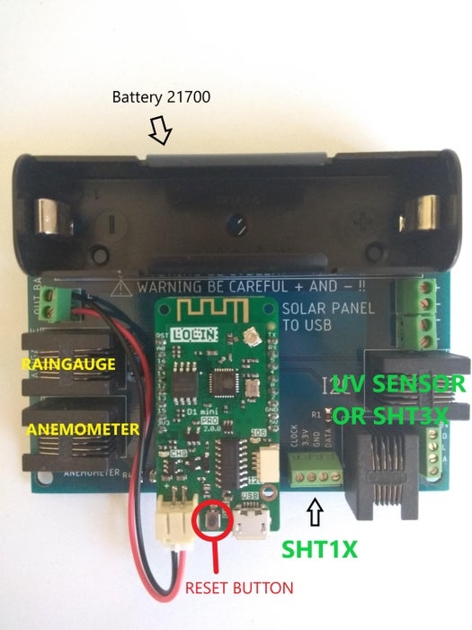
1.Install the board in weather proof box as example below and install the battery (BE CAREFUL + AND – AND BATTERY SHOULD BE 100% CHARGED BEFORE FIRST START):
2. Connect all the available sensor on the board using the RJ12 connectors or the screw terminal, depending on the type of sensor used. (Refer to the list of ‘Compatible sensor and specification) (SENSORS ARE CONNECTED WITH AN ADAPTOR BOARD DESIGNED SPECIFICALLY FOR THE SHT3X AND UV SENSORS AND ALSO ONE FOR THE SHT35 ON TINDIE ) SEE PHOTOS
3. Plug IN the battery connector into the Wemos D1 Mini Pro and setup the Wi-Fi connection same as DEVICE 2. Name of the network will be ‘LineaMeteoStazioneS’
After that plug in also the USB from the solar panel converter. (The photo is just representative of a prototype and the USB converter will be already connected for you, you will just need to connect the solar panel)
Step 5: Configure Weather Station Settings With Firebase
EVERY SETTINGS MADE REQUIRES TO DISCONECT FROM POWER
DEVICE 2 AND RECONNECT TO POWER
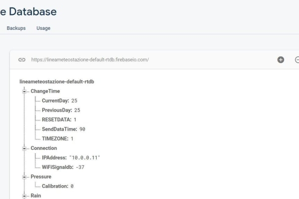
After followed the procedures above you will find that your real time database will look like this(if UV index sensor is connected it won’t shows 655):
The database is categorized as following:
· ChangeTime
This option is used to set your TIMEZONE which will be your time (need to modified when day light saving apply) and to set the SendDataTime. It is recommended to don’t upload the data faster than 90 seconds to save the battery life of DEVICE 1
CurrentDay and RESETDATA don’t need to be touched. To reset all data in database enter 0 in RESETDATA.
· Connection
Connection is used to know your current IP address of DEVICE 2 and to monitor the Wi-Fi signal strength of DEVICE 1. Try to keep DEVICE 1 with at least -75 or more of signal strength.
IPAddress can be used to port forwarding the IP in order to setup your devices in the LineaMeteo weather network. (PortForwarding can be done in the router, but every router is different, so you need to know yours. External port should be 4600 and internal port should be 80, example below)
· Pressure
Here is stored the value of the Pressure and also is possible to Calibrate it based on sea level. Refer to some near weather station or looking the current atmospheric pressure on the forecast. Every number means 1Pa
· Rain
Here is stored the value of the rain in 24H and also other values related to the rain. You can use every tipping bucket rain gauge so this means that you will need to calibrate how much every tipping count for. Modify ‘mmGoccia’ to change the tipping count in mm. Default is 0.2mm
· SHT1x
This contain the data of the Sensirion SHT1x or SHT7x series.
· SHT3x
This contain the data of the Sensirion SHT3x series.
· Services
This contain all the services available to use with this weather station.
OPENWEATHER
You can setup your own account on OpenWeather for current condition weather description on DEVICE 3 (find My API Keys and copy in the API in Services, OpenWeather.)
Hemisphere type north if you live in northern hemisphere or south in southern hemisphere to display correct astronomy section on display.
Language ‘en’ or ‘it’ to change from English to Italian on DEVICE 3.
Latitude and longitude to display correct weather condition description on DEVICE 3
If from southern hemisphere it will be a negative number on Latitude.
THINGSPEAK
Create an account on ThingSpeak and find the WriteAPIkey and copy in myWriteAPIKey, to see the difference with graphics between the SHT1x and SHT3x series if connected the 2 sensors or to just monitor the SHT1x
WeatherCloud
You can link the weather station to Weather Cloud network using this option. Go to Settings on your devices and select ‘Link’, it will give you the ID and Key that you can copy in the database.
WunderGround
You can link the weather station to WunderGround using this option.
Find the ID and Key on My Devices and copy it to the database.
· Sleep
By default is set to 1 but can be changed to 0 to enable the sleep mode. In sleep mode the rain gauge and anemometer will not work so they have to be disconnected from PCB
Sleep mode if used on battery will last average of 6 months without recharging the battery with the solar panel.
· UVIndex
This contain the value of the current UVindex.
· Wind
This contain the values of the Wind, like degrees of the Wind Direction and also the Wind Speed and the Gust. It can be adjusted the Offset here, in order to point the right direction of the Wind Direction. 0 degrees or 360 degrees should be point North.
Step 6: Setup DEVICE 3 DISPLAY (MORE PHOTOS AVAILABLE IN GITHUB)
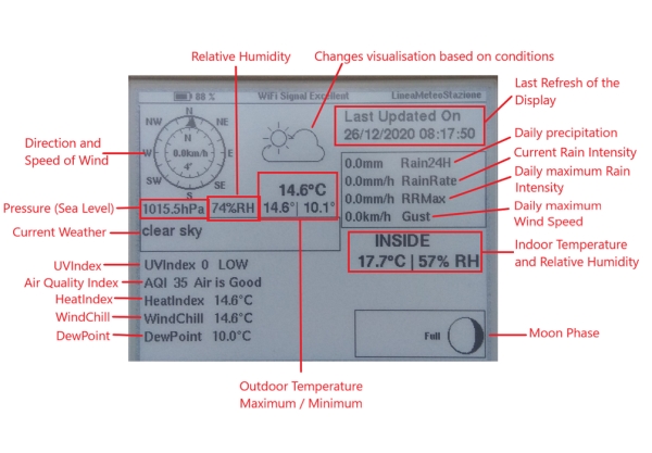
The DEVICE 3 is powered up with one single battery 18650, which can be recharged trough USB as shown in photo (The photo doesn’t represent the final project but just the prototype, inside it will have a proper PCB design.) The little circle shows the BME680 sensor.
The display refresh every 20 minutes automatically and every 1 hour after midnight and until 7AM. But It can be refreshed manually clicking on the button on the right side of the box.
ONCE REFRESHED IT WILL ALSO CHANGE THE LANGUAGE SELECTED IN SETTINGS IN FIREBASE
After the battery has been installed follow the same procedures of DEVICE 2 to connect to Wi-Fi.
Name of the network will be ‘LineaMeteoStazioneVisual’
The battery should be sufficient charged before start.
Step 7: COMPATIBLE SENSORS(MORE INFORMATION ON GITHUB)
Temperature/humidity MAIN: SHT3x series Sensirion. Accuracy refer to datasheet of each
sensor.
Temperature/humidity SECOND (can be used for soil temperature and moist) : SHT1x and SHT7x series Sensirion. Accuracy refer to datasheet of each sensor.
Temperature, Humidity, Air quality Indoor: BME680
Pressure: BMP180
Rain Gauge: Every tipping bucket rain gauge, adjustable resolution. WHEN ADJUSTED RESOLUTION IT MAY TAKES UP TO 3 HOURS TO CHANGE THE SETTINGS ON DEVICE 1. This is because the device goes to sleep every 3 hours to save energy if no rain is detected. When it wakes up, it will check the settings again. You can also manually reset by clicking the reset button as shown in photo before.
Anemometer: Davis Anemometer
UVIndex: SI1145