This Power Timer is based on the timer presented at:
https://www.instructables.com/id/Timer-With-Arduin…
A power supply module and an SSR (solid state relay) were attached to it.
Power loads of up to 1KW can be operated and with minimal changes the load power can be increased.
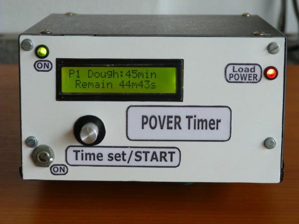
The choice of timer duration or program number is set from the Rotary Encoder located on the front panel. This is also where the timing starts. The LCD1602 displays the initial time duration, the program number but also the remaining time.
The load is connected to the Power Timer via a wall-mounted socket (on the back of the box).
I wrote a new program for this variant, according to the needs of power applications.
The applications cover a wide range:
mixer motors, water pumps for garden watering, heating elements, etc.
Supplies
All components can be found on AliExpress at low prices.
From my own workshop I used the metal box (from the power supply of an old PC), connecting wires, screws, nuts, spacers and plastic foils.
The power supply is made on a separate PCB, made by me and designed in KiCad. About this in a future Instructables.
The box is not painted but wrapped in a self-adhesive foil that can be found at any DIY store.
Step 1: Schematic Diagram
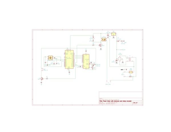
An SSR type SSR-40 DA is attached to the module built from the previous internet address (see Intro), after the classic relay has been removed from the board.
The power supply of the device is made from a transformer that delivers approx. 14Vac / 400mA.
This is followed by a filtration with C4 = 1000uF / 25V and stabilization with U2 7812, obtaining 12V.
D3 indicates the presence of supply voltage, while D1 indicates the presence of voltage on the load.
Otherwise, the scheme is identical to the one from the internet address in Intro.
Step 2: List of Components, Materials, Tools.
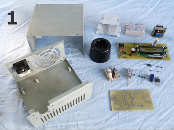
-SH metal box from an old PC.
– Timer With Arduino and Rotary Encoder 1pcs.(as in Intro).
-SSR-40 DA and heatsink 1+1 pcs.
-L7812 and heatsink 1+1 pcs.
-1N4001 4 pcs.
-1000 uF/25V 1 pcs.
-10uF/16V 1 pcs.
-Resistor 1,5K/0.5W 1pcs.
– LED R, LED G 5mm. 1+1 pcs.
-Fuse holder and fuse 6,3A 1+1 pcs.
-Switch power 1 pcs.
-Transformer that delivers 14V / 0.4A in secondary 1pcs.
-Wall socket -1 pcs
-PCB for supply module 1pcs.(KiCad project) 1 pcs.
-Silicon grease (see photo 2)
-Matt white plastic foil(photo 6).
-Self-adhesive foil approx.16X35 cm.(photo 9).
-Screws, nuts, spacers (photo 10).
-Screwdrivers
-Digital multimeter (any type).
-Fludor, soldering tools, cutter for component terminals.
-Tools for metal drilling, filing, metal cutting for mechanical processing of the box
(you have to be friends with them to do the work).
-Lust for work.
Step 3: SSR and Power Supply Assembly.
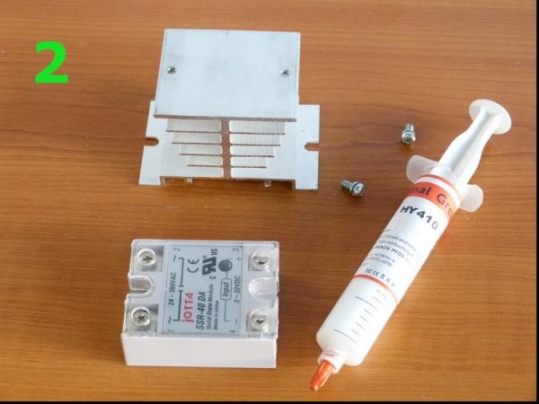
It is made according to the electrical diagram and photo 2, 3, 4, 5.
Step 4: Mechanical Processing and Box Cover.

-The mechanical processing of the box is make according to the dimensions of the subassemblies (photo 7, 8).
-Cut the 2 matt white plastic sheets as in photo 6. Then glue them on the front and rear panel of the box.
-We cover the lid of the box with a self-adhesive foil as in photo 9.
Step 5: Mounting the Subassemblies in the Box.
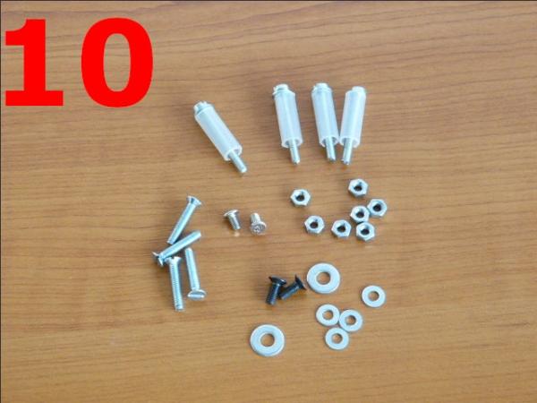
-Using the items from photo 10, the subassemblies are assembled as in photo 11, 12, 13.
Step 6: Wiring and Putting in Function.
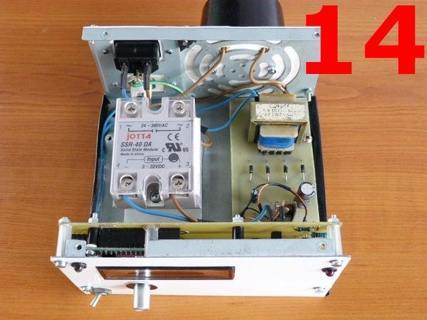
-The wiring is done according to the schematic diagram and photo14,15.
-On the power circuit the wires must be thick enough to withstand currents of 6 A. (minimum 2 mm. diameter).
They must have good quality insulation!
Warning!
This device works with dangerous voltages for the manufacturer as well as for the user!
It is strongly recommended that the manufacturer be a person with experience in the electrical field.
For the protection of the user, special attention will be paid earthing the box, using a socket and earthing cable. Be careful when connecting the white-green grounding cable (photo 14,15).
-Putting in function is done by measuring the voltages according to the schematic diagram with the digital multimeter, loading the software as shown below and entering a value for timing. Check that it is executed correctly.
Step 7: Software
There are some programs written by me at the addresses:
https://github.com/StoicaT/Power-timer-with-arduin…
https://github.com/StoicaT/Timer-with-Arduino-and-…
https://github.com/StoicaT/Timer-with-Arduino-and-…
The first variant has a number of predefined programs that allow the ON / OFF type operation for a defined period used on a motor that operates a dough machine.
On the same principle, with simple changes in the program you can operate a water pump for watering the garden.
The last two program variants refer to a classic countdown timer with two different display modes.
The github repository explains what each one does and how the timer is programmed in each case.We will download the desired version and upload it to the Arduino Nano board.
And that’s it!
Source: Power Timer With Arduino and Rotary Encoder